ET-P1101 – A DIY ESPHome Panasonic Climate interface
Table of Contents
Getting the Panasonic Climate control off the cloud
Back in August 2021 we published an article about an esphome component for a esp32 or esp8266 based airconditioning/Climate Wifi interface. A great way to get your Panasonic Climate control off the Panasonic Comfort Cloud and into Home Assistant locally. The only thing missing was a proper hardware solution, so we developed one and published the article here.
This SMD design perfectly replaces the original Panasonic Climate interface and even fits the original enclosure. The only disadvantage was that a SMD design is extreme hard to build yourself. We received a lot of requests to sell a pre-build interface. Those soon where sent all over the planet which cost us loads of time. That is not what we are about. We want to design hardware that you can easily build yourself, so we now finally publish our DIY version of the Panasonic Climate Interface. It’s easy to build, but still perfectly replaces a Panasonic DNSK-P11 or CZ-TACG1 WiFi interface.
How does it work?
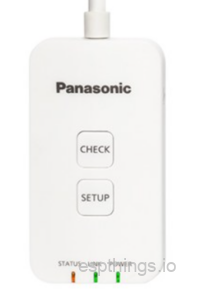
Panasonic Climate units are usually connected to Panasonic’s Comfort Cloud using either a DSNK-P11 or a CZ-TACG1 WiFi interface.
 CZ-TACG1 |
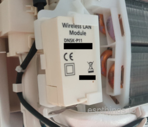 DNSK-P11 |
If you have one of these interfaces installed, you are unfortunate enough to be using the Panasonic Cloud service which sucks! Repeatedly having to log-in to your app and not not being able to control your Climate unit due to Cloud service outages are common issues. If you do not have one of these interfaces installed, you are likely not able to control your Climate units by anything else then the standard remote control that comes with the Climate unit.
The Solution
There is a solution to these problems. A custom esphome module allows you to connect Home Assistant to your Panasonic Climate locally. Remote controlling your Climate unit will be instant and no longer cloud dependent. Now the only thing needed is some hardware to act as the bridge between Home Assistant and the Panasonic Climate.
Design parameters
Our requirements:
- Must be able to connect to both the CN-CNT and the DNSK-P11 connector
Must work as a DNSK-P11 or CZ-TACG1 replacement - Preferably have the same size as the original interface
- Must support an external DS18B20 temperature sensor
- Must have a Micro-USB or USB-C terminal for esphome installation
- Enclosure must be readily available or 3D printable
So we designed a doughterboard PCB for a ESP8266 D1 mini sized module. After some testing we where unable to get this working stably. Modules differ from one Aliexpress or Amazon order to the other and this design suddenly stopped working after just reclacing the ESP8266 D1 Mini. After that we started testing the pin-compatible ESP32 D1 Mini. This worked reliably in all cases, but unfortunately the size of the ESP32 D1 mini is a lot wider and therefor not suited for our needs. We also tested a different design with different components, but that proved hard to build for a regular consumer. Finally we tested out initial design using the new ESP32 C3 Mini and that proved to work perfectly and fit within our size constraints.
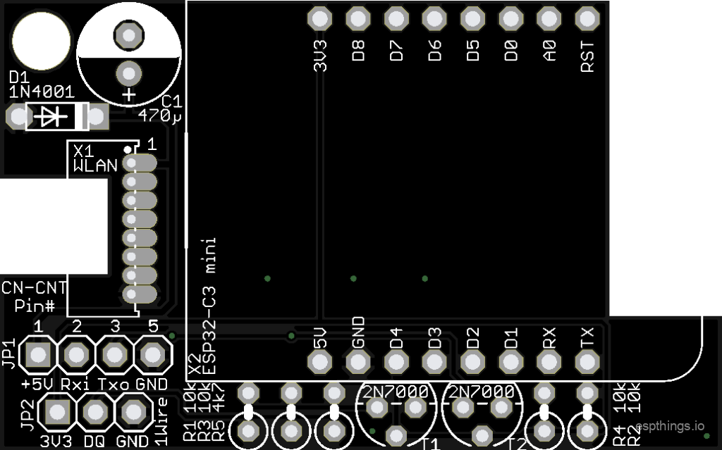
PCB design
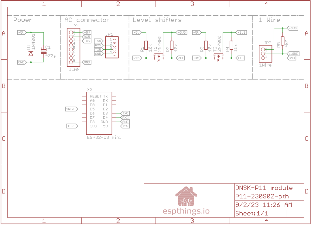
We where able to come up with a simple yet effective design using only 9 simple components. Add the ESP32-C3 Mini and a connector and you have yourself a working Panasonic Climate Interface for Home Assistant.
Schematic
PCB

Bill of materials
See below the list with the components you will need to build the Espthings ET-P1101 controller. A number of these items will not be sold in smaller quantities at AliExpress. We will try to use the same components as much as possible in other projects.
We would really appreciate it if you will use the links below to buy the components, since it will give a little bit of commission to us without any additional cost for yourself. These commissions will be used to cover some of the costs involved in the development of the design.
| Reference | Quantity | Description | Affiliate |
| ESP32-C3 mini | 1 | ESP32-C3 Mini (comes with 2 strips of 8-pin headers) |
Link |
| T1, T2 | 2 | 2N7000 TO92 Small Signal MOSFET 200 mAmps, 60 Volts | Link |
| D1 | 1 | 1N4001 | Link |
| C1 | 1 | 470µF / 10V or 16V 6mm diameter, 2.54mm pitch | Link |
| R1, R2, R3, R4 | 4 | Resistor 10KΩ | Link |
| R5 | 1 | Resistor 4.7KΩ | Link |
| JP1 | 1 | 5 pin PAP-05V-S connector with wires (cut duponts and solder!) Only needed for CZ-TACG1 If 20cm is not long enough for you, order this one |
Link |
| JP2 | 1 | Optional: Wired DS18B20 temperature sensor | Link |
| Enclosure | 1 | 3d-Printable Enclosure, specifically for this interface | Link |
| X1 | 5 | 1.27mm pin header Only needed for DNSK-P11 |
Link |
| PCB | 1 | PCB ET-P1101 from PCBway | Link |
Putting it together
| DISCLAIMER: We are frequently receiving questions from commercial hardware stores about our designs. How to build, which component or connector to use etc. We are all about DIY. If you can not build this module yourself using our instructions and some basic knowledge, please do not acquire them from commercial hardware stores, but abandon this project all-together. If you are however building this yourself and you have any further questions, you may post those in the comments and we will do our best to answer those in due time. |
Like with all other projects, it is the easiest to start with identifying the components purchased as discussed in the blog post. After sorting the components and cleaning the PCB, start with the lowest components first. For this project, we advise to work in this order:
- DNSK-P11 header* (not required if you are attaching it to the CN-CNT to replace a CZ-TACG1 Wifi module)
- Diode
- MOSFETs
- Resistors
- Electrolytic capacitor
- ESP module headers (Use the hints in the soldering blog post!)
- CZ-TACG1 cable (only If you are attaching it to CN-CNT connector)
* Use a very small soldering tip for the 1.27mm headers and use minimal amount of soldering wire. Make sure it melts and flows out siffuciently.
Once all components are soldered in place, perform a good visual check of all joints, and pay particular attention to possible solder bridges (unwanted solder connections between pins). Do not forget to clean the excess solder flux from the PCB using alcohol!
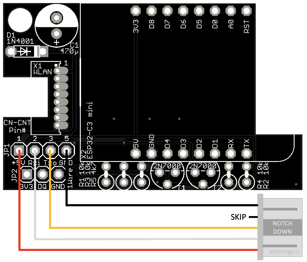
Wiring
Finished module
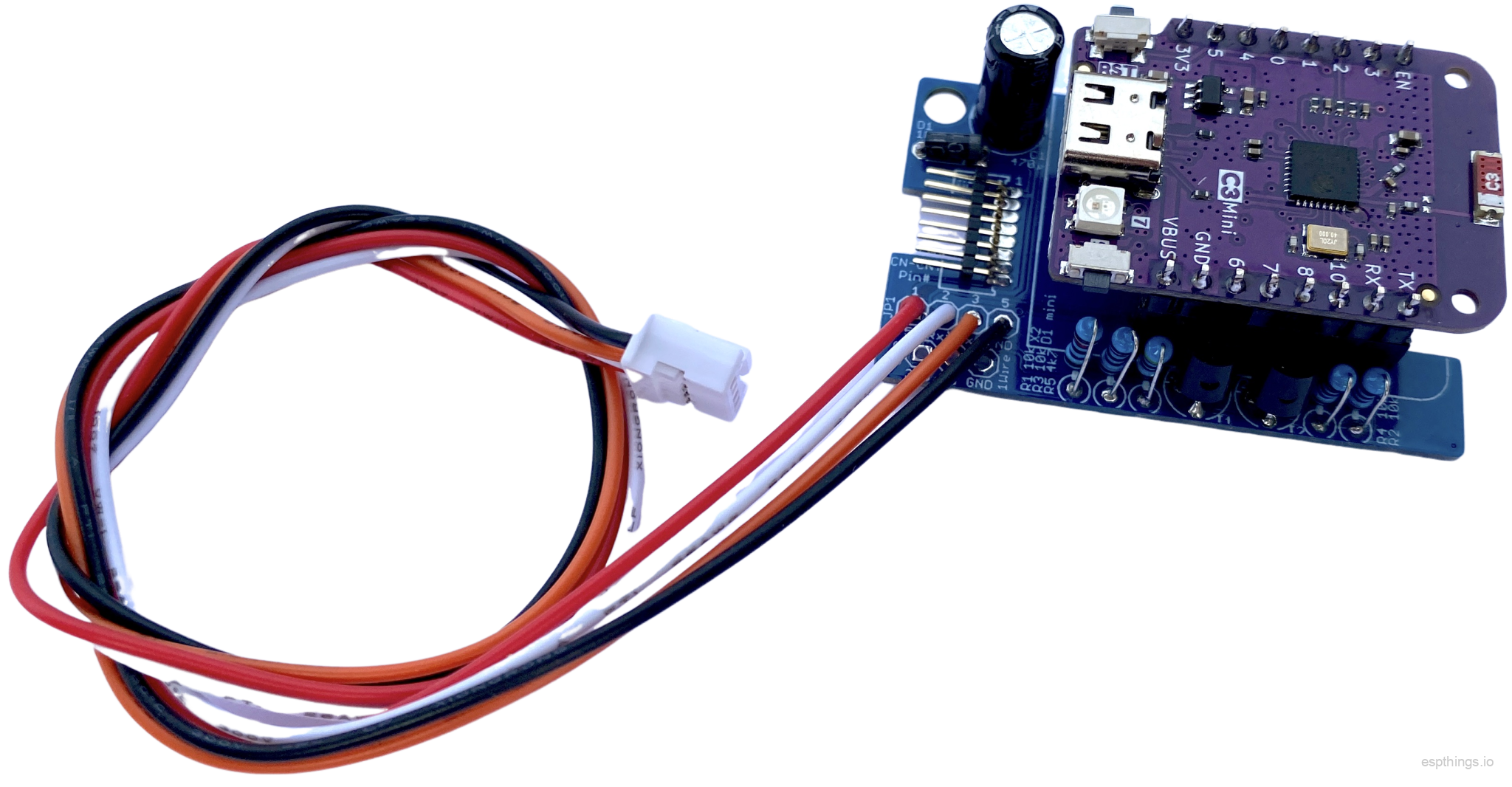
In this case with both the DNSK-P11 header and the CN-CNT cable soldered. You only need one of both, depending on your climate unit!
Installation
DNSK-P11 replacement:

Original DNSK-P11 enclosure
Below a video on how to install the original CZ-TACG1 interface. The interface is different, but you’ll find clear instructions on how to open and close the unit. After taking off the enclosure, check your Climate unit for the DNSK-P11 enclosure.

Please subscribe to our YouTube channel and hit the bell to never miss a (esp)thing!
Take the DNSK-P11 pcb out of the enclosure carefully, remove the black connector from the PCB and install your espthings P11 interface. Connect the interface using the original DNSK-P11 cable. The connector-lip needs to go downwords in the notch of the PCB, the flat part of the connector up.
Please be careful as the pins are tiny. If you use your brain in stead of brute force, you’ll be ok. 🙂
CZ-TACG1 replacement:
You can eiher replace the original CZ-TACG1interface, or if you have no Wifi interface installed yet and your Panasonic unit has the 5-pin CN-CNT connector, you are good to install the espthings.io Wifi interface.

CN-CNT connector
Below a video on how to install the original CZ-TACG1 interface. The installation of the espthings interface with the cable (option 5), is pretty straight forward.
Please subscribe to our YouTube channel and hit the bell to never miss a (esp)thing!
Software
esphome config
Create a new esphome device and use the following configuration example:
substitutions:
    devicename: "espthings-p11-diy"
    long_devicename: "ESPthings P11 DIY"
    pcb_version: "230902"

esphome:
  name: "${devicename}"
  name_add_mac_suffix: false ## if 'false' use different names/hostnames for each device!
  comment: "${long_devicename} ${pcb_version}"

esp32:
  board: esp32-c3-devkitm-1
  framework:
    type: arduino
  variant: ESP32C3

external_components:
  source: github://DomiStyle/esphome-panasonic-ac
  components: [panasonic_ac]

wifi:
  ssid: !secret esphome_wifi_ssid
  password: !secret esphome_wifi_password
  ap:
    ssid: "${devicename} Hotspot"
    password: qwe12345

captive_portal:

web_server:
  port: 80

logger:
  level: DEBUG

api:
  password: !secret esphome_api_password

ota:
  password: !secret esphome_ota_password

uart:
  tx_pin: GPIO7
  rx_pin: GPIO6
  id: ac_uart
  baud_rate: 9600
  parity: EVEN

## It possible to wire an optional temperature sensor
## DS18B20 1-wire Temperature Sensor
#dallas:
#  - pin: GPIO01
#sensor:
#  - platform: dallas
#    # Check the dallas sensor address in the log file
#    # For more info: https://esphome.io/components/sensor/dallas.html
#    address: 0x540000001524be28
#    name: "$long_devicename Temperature"
#    id: temp

switch:
  - platform: restart
    name: "$long_devicename Restart"

climate:
  - platform: panasonic_ac
    type: cnt
    ### or change "cnt" into "wlan" for DNSK-P11 ###
    name: "${long_devicename}"
    vertical_swing_select:
      name: "${long_devicename} Vertical Swing Mode"
    outside_temperature:
      name: "${long_devicename} Outside Temperature"

## If the ac does not report a current temperature (CZ-TACG1 only) uncomment
## the line below and point to the appropriate sensor
#
#   current_temperature_sensor: temp
#
## Since Panasonic ACs support different features you can comment out the lines below if applicable:
#
#   eco_switch:
#     name: Panasonic AC Eco Switch
#   nanoex_switch:
#     name: Panasonic AC NanoeX Switch
#   mild_dry_switch:
#     name: Panasonic AC Mild Dry Switch
#   econavi_switch:
#     name: Econavi switch
#   current_power_consumption:
#     name: Panasonic AC Power Consumption
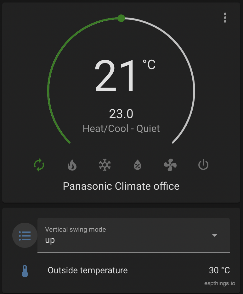
Home Assistant lovelace config
type: vertical-stack
cards:
- type: thermostat
entity: climate.your_p11_interface_name
- type: entities
entities:
- entity: select.your_p11_interface_name_vertical_swing_mode
- entity: sensor.your_p11_interface_name_outside_temperature
End result 🙂
Please subscribe to our newsletter!

Hi,
I am keen to add wifi connectivity to HA to 5 Panasonic aircon units in my holiday home in Spain and would love to be able to implement your solution.
However I would, if possible, much prefer to buy pre-built PCB’s than order all the separate components and then have to wait for 2 months (standard shipping) for the bits to arrive! I also appreciate that you don’t want the hassle of sending out units worldwide yourselves!
I see you have put the PCB spec on PCBWay and I can get them to make them for me. PCBWay also offer a PCB assembly service but I don’t think you have submitted the list of components and their board locations to PCBWay to enable them to supply pre-assembled units. Any reason why?
I would have thought it would be a perfect solution for you in that you’d get a 10% commission on a much higher value spend and your followers could get fully assembled boards much quicker (1 week?) and with much less hassle than having to order the components and build it themselves, should they choose to do so? I certainly would!
If we would put the pre-build smd-version on PCB-way you would still have to solder parts yourself as not all parts can be placed by PCB-way.
Now all the bits have finally arrived, I am assembling the boards and have just added the first cable but suspect the ones supplied (via your link) are wired the opposite way round to your picture of the finished module, and the one you point Bill Collins to here (bottom photo)? Photo of mine attached. Am I right in assuming the numbers (1,2,3,5) on the PCB correspond with the numbered pins on the CN-CNT plug? So on the cables supplied to me, 1=Black,2=Red,3=White and 5=Orange?
Hoping to get these finished so I can take them out to my house in Spain on friday – very much looking forward to installing them! Like Oliver M., I still wish I could have bought them fully assembled, though! You deserve to get more out of this.
Please check this thread as the question has been answered before.
https://github.com/DomiStyle/esphome-panasonic-ac/blob/master/README.CZTACG1.md
Thanks so much for this, I only found the post after you guy’s stopped shipping them. There is a comment on PCB-way is that something I should wait to be addressed before ordering?
No, the 1.27 pitch pins fit just fine.
I already have a whole bunch of Wemos ESP32 D1 mini at home that I was thinking of trying to use for this purpose. Is there any possibility to post the circuit diagram as well?
Thanks in advance!
??? https://www.espthings.io/index.php/2023/09/02/esphome-panasonic-climate-interface/#Schematic
Sorry, my bad I wasn’t clear enough. I meant a pure electrical circuit diagram, not the PCB wiring diagram ie
You should be able to create something just fine using this schematic. It clearly say’s how everything is connected.
However, there is no need to change anything for esp32 wemos d1. It will fit just fine, you only need a bigger enclosure.
Hey, I’ve ordered some of the boards and components and putting it altogether. I had some of the connectors for the CN-CNT connector already but I’m not sure of the pin out from the connector on the AC to map them properly. Do you have to have a pinout for the connector on the ACs?
Googling it is getting me more confused so it would be hugely helpful
Check:
https://github.com/DomiStyle/esphome-panasonic-ac/blob/master/README.CZTACG1.md
Hello. This is great.
I have also connected a Wired DS18B20 temperature sensor. Which GPIO is this mapped to? Possible configuration for this?
Sorry, missed your question. Try:
## For revisions from 220722-01 and higer the optional temperature sensor is available.## DS18B20 1-wire Temperature Sensor
#dallas:
# - pin: GPIO18
#sensor:
# - platform: dallas
# # Check the dallas sensor address in the log file
# # For more info: https://esphome.io/components/sensor/dallas.html
# address: 0x540000001524be28
# name: "$long_devicename Temperature"
# id: temp
This config works for you?
Hello,
I have got 6 Panasonic aircons. I really appreciate your project, because I do not like cloud solutions in my home automation and knx interface would be six times 350€.
My soldering skills are really poor. PCBWay is offering an assembly solution. I filled the bom as far as I could, but some affiliate links do not work anymore. My electicals skill are also limited, so I do not have a clou what to put instead.
Can you give me advice? May be there are more like me, who would order already assembled devices with PCBWay. Components are C1, R1-R4 and R5
Many thanx in advance
Oliver
Hi, all links in the BOM work for me, so I don’t understand your issue. Anyway, there is a good description of the part in the BOM, so you should be able to find the parts easily on aliexpress of locally from a store.
Hi Michel, thank you for this wonderful project. it is addressing exactly the use-case i was looking for.
However, i a technical issue.
I ordered all the parts you suggested (from the ALI links you provided), but i cannot get the ESP to connect to the WIFI.
i was googling a bit on this LOLIN ESP board, but there seems to be wifi problems with it.
I was wondering if you or other builder had experienced this when building this project?
And if so, how was it resolved.
I have also reached out to Lolin support on Aliexpress, but it would be good to get the community feedback.
The ESP32-C3 board you are using is the exact one from the link in the BOM?
yes. clicked the link and ordered at Ali.
I got the V2.1.0 version, which is supposed to be better then the v1.0.0 version. However, i am still struggling.
If you dont have any immediate recognition of this issue, i will dig a bit more. Perhaps i can load it with some other firmware (tasmota) to validate the HW.
I have the 2.1.0 as well. Please post your config in code tags. It’s impossible to say what goes wrong without the config.
Same problem here (same parts, v2.1.0 from the Ali link). When flashing the bin into the ESP module I get a bunch of errors. After some google, I also read that the C3 has issues.
substitutions:
    devicename: "ac-test"
    long_devicename: "AC Test"
    pcb_version: "230902"

esphome:
  name: ac-test
  name_add_mac_suffix: false ## if 'false' use different names/hostnames for each device!
  platformio_options:
    board_build.flash_mode: dio
  comment: "${long_devicename} ${pcb_version}"
  friendly_name: ac-test


esp32:
  board: esp32-c3-devkitm-1
  framework:
    type: esp-idf
  variant: ESP32C3


external_components:
  source: github://DomiStyle/esphome-panasonic-ac
  components: [panasonic_ac]


wifi:
  ssid: !secret wifi_ssid
  password: !secret wifi_password
  ap:
    ssid: "${devicename} Hotspot"
    password: ########

captive_portal:

web_server:
  port: 80

logger:
  level: DEBUG


# Enable Home Assistant API
api:
  encryption:
    key:#########


ota:
  password: #######


uart:
  tx_pin: GPIO7
  rx_pin: GPIO6
  id: ac_uart
  baud_rate: 9600
  parity: EVEN


switch:
  - platform: restart
    name: "$long_devicename Restart"

climate:
  - platform: panasonic_ac
    type: cnt
    ### or change "cnt" into "wlan" for DNSK-P11 ###
    name: "${long_devicename}"
    vertical_swing_select:
      name: "${long_devicename} Vertical Swing Mode"
    outside_temperature:
      name: "${long_devicename} Outside Temperature"
I added the line:
based on some google results, and at least it wont boot loop lock. If left to the default ‘qio’, the board enters a boot loop and I need to erase the flash all together before trying anything else.
With that config, If I check the logs I get (see below) but the device don’t connect to the wifi nor creates a hotspot.
Very strange….
My config;
substitutions:
  devicename: esp32-airco-01
  long_devicename: Panasonic Airco kantoor
  pcb_version: "220722-01"

esphome:
  name: "${devicename}"
  name_add_mac_suffix: false
  comment: "${long_devicename} ${pcb_version}"

esp32:
  board: esp32-c3-devkitm-1
  framework:
    type: arduino
  variant: ESP32C3

external_components:
  source: github://DomiStyle/esphome-panasonic-ac
  components: [panasonic_ac]

wifi:
  ssid: !secret esphome_wifi_ssid
  password: !secret esphome_wifi_password
  ap:
    ssid: "${devicename} Hotspot"
    password: !secret esphome_ap_password

captive_portal:

web_server:
  port: 80

logger:
  level: DEBUG

api:
  encryption:
    key: !secret esphome_api_key

ota:
  password: !secret esphome_ota_password

uart:
  tx_pin: GPIO7
  rx_pin: GPIO6
  id: ac_uart
  baud_rate: 9600
  parity: EVEN

switch:
  - platform: restart
    name: "$long_devicename Restart"

climate:
  - platform: panasonic_ac
    id: kantoor
    type: cnt
    name: "$long_devicename"
    vertical_swing_select:
      name: "$long_devicename Vertical Swing Mode"
    outside_temperature:
      name: "$long_devicename Outside Temperature"
    current_power_consumption:
      id: power_consumption_kantoor
      name: "$long_devicename Power Consumption"
      unit_of_measurement: W
      accuracy_decimals: 0
      device_class: power
      state_class: measurement

sensor:
  - platform: total_daily_energy
    name: "$long_devicename Total Daily Energy"
    power_id: power_consumption_kantoor
    filters:
        - multiply: 0.001
    unit_of_measurement: kWh
    device_class: energy

time:
  - platform: homeassistant
    id: my_time
OTA flash:
Framework is different. You use ‘arduino’ where I use ‘esp’idf’ as per the example. I’ll try that one, not sure if it will make a difference (I’m still new into this ESP bussiness 😛 )
I changed the framework and it kinda worked. First time I plugged it into the AC unit, it took ~1min and I started getting data on my ESPHome, but after 2~3min running, I got a timeout and that was it, can’t connect anymore.
That should prove that the config works, but now I need to figure out how to debug that DC and how to make it more reliable :/
During the weekend I was able to properly test/debug many options. Now I have a reliable configuration (flashed to other boards and work like a charm).
My last iteration is:
substitutions:
  devicename: esp32-airco-server
  long_devicename: Panasonic Aircon Server
  pcb_version: "230902"


esphome:
  name: "${devicename}"
  name_add_mac_suffix: true ## if 'false' use different names/hostnames for each device!
  comment: "${long_devicename} ${pcb_version}"
  platformio_options:
    board_build.flash_mode: dio


esp32:
  board: esp32-c3-devkitm-1
  framework:
    type: arduino
  variant: ESP32C3


external_components:
  source: github://DomiStyle/esphome-panasonic-ac
  components: [panasonic_ac]


wifi:
  ssid: !secret wifi_ssid
  password: !secret wifi_password
  manual_ip:
    static_ip: xxx.xxx.xxx.xxx
    gateway: xxx.xxx.xxx.xxx
    subnet: xxx.xxx.xxx.xxx
  ap:
    ssid: "${devicename} Hotspot"
    password: xxxxxxxx
  output_power: 8.5db
  power_save_mode: none

captive_portal:

web_server:
  port: 80

logger:
  level: VERBOSE


# Enable Home Assistant API
api:
  encryption:
    key: "xxxxxxxxxxxxx"


ota:
  password: "xxxxxxxxxxxxx"


uart:
  tx_pin: GPIO7
  rx_pin: GPIO6
  id: ac_uart
  baud_rate: 9600
  parity: EVEN


switch:
  - platform: restart
    name: "$long_devicename Restart"

climate:
  - platform: panasonic_ac
    id: ac_server
    type: cnt
    name: "$long_devicename"
    vertical_swing_select:
      name: "$long_devicename Vertical Swing Mode"
    outside_temperature:
      name: "$long_devicename Outside Temperature"
    current_power_consumption:
      id: power_consumption_ac_server
      name: "$long_devicename Power Consumption"
      unit_of_measurement: W
      accuracy_decimals: 0
      device_class: power
      state_class: measurement
    nanoex_switch:
      name: Panasonic AC NanoeX Switch
      icon: mdi:air-filter


sensor:
  - platform: total_daily_energy
    name: "$long_devicename Total Daily Energy"
    power_id: power_consumption_ac_server
    filters:
        - multiply: 0.001
    unit_of_measurement: kWh
    device_class: energy


time:
  - platform: homeassistant
    id: my_time


# For revisions from 220722-01 and higer the optional temperature sensor is available.
# DS18B20 1-wire Temperature Sensor
dallas:
  - pin: GPIO18
#sensor:
# - platform: dallas
# # Check the dallas sensor address in the log file
# # For more info: https://esphome.io/components/sensor/dallas.html
# address: 0x540000001524be28
# name: "$long_devicename Temperature"
# id: temp
To consider:
Although I have the board version 2.1.0, it looks like reducing the wifi power output and disabling the power save mode, helps with the frequent disconnections.
I had to manually setup my ip address, since for reason mDNS is not working properly on my network.
Also network related, I setup a second access point to handle only my ESP devices (I suspect that my main AC was getting overload with too many devices connecting at once).
I kept the ‘arduino’ framework as per your configuration.
I’m pretty sure that I have the dallas sensor properly connected, but I still get on my logs:
Do you have any hint on how to make it work?
Try GPIO22, I might have mistakenly assumed the GPIO (18) was the same on this board.
I don’t think it has GPIO22. Based on this
https://docs.espressif.com/projects/esp-idf/en/latest/esp32c3/api-reference/peripherals/gpio.html
It only seem to have from 0 to 21. Also I’m not sure if the ‘mini’ is different than the plain ESP32 C3
Same physical location, different GPIO number, It should be GPIO10!

I guess that with trial and error I’m going to get good at this. Not GPIO10, but GPIO1 !
d5 on you schematics seem to connect to pin 1 (green value) on that picture, and looking at
https://www.wemos.cc/en/latest/_static/files/sch_c3_mini_v2.1.0.pdf
that corresponds to GPIO1.
Also,
Thanks for all your help Michel!!
Not sure if my previous comment was sent. GPIO10 didn’t work, but looking at your diagram D5 seems to align with GPIO1 (https://www.wemos.cc/en/latest/_static/files/sch_c3_mini_v2.1.0.pdf)
And once switched to that GPIO, it worked like a charm.
Thanks for all your help Michel!
Sorry about that. We had so manny iterations of this pcb and esp’s, I was unsure about the sensor as we never actually that on this particular version. Glad it works!
Guys, i thought would be good to give an update on my project.
I manage to get 2 devices working. The config posted above is proven to be working.
I had to add the “output_power: 8.5db” command to get the wifi working.
Couple of questions/comments:
1) what is the purpose of this nanoex_switch? I have removed it for now untill someone explain where its good for
nanoex_switch:
      name: Panasonic AC NanoeX Switch
      icon: mdi:air-filter
2) I suggest to @michel you add a clear diagram of the wiring of the cable. I was struggling with this and i think i destroyed 2 ESP devices as a result of wrong wiring. There are some links to other projects where this wire is used, but even that was not good enough. Now ordering some new ESP’s to try to get the last airco working.
NanoeX is a air purifying feature on Panasonic Climate Units. If you do not have the feature, don’t configure. This is clearly documented on Dominik’s github repo.
Even though (also documented clearly on Dominik’s github repo) it should be clear how to wire, the just added schematic should make things even easier 😉
I have managed to get two of your boards working and installed in my Panasonic CS-ExxPKEW units with CN-CNT cables, although it is really difficult to access and connect to the CN-CNT socket (on the main PCB and just behind the bottom two connectors) and there is no provision for fitting a wifi module anywhere at the front of the unit. My units must be night on 10 years old so probably way before wifi modules were even considered.
Many thanks for adding the cable diagram as the cables I was supplied with (via your link) are definitely wired the opposite way around to yours! Might I also suggest you add the pin numbers to the diagram – if I am not mistaken, 5 is at the top and 1 at the bottom (with latch on the underside). It looks like my diligence on this might have saved me blowing a couple of the ESP boards!
I also had problems with the encryption key using a common | secret esphome_api_password as it appears each board needs a unique key which is set differently each time you run ‘prepare for first install’ using web.esphome.io. Clicking and copying the newly generated encryption key into the yaml code seemed to work fine for me.
I also had huge issues with wifi dropping out so much that I could rarely load the devices web server page properly, but I eventually found comments elsewhere on adding the output_power: 8.5 to the wifi section and all is now working reliably. I suggest you might want to add it to your code? Maybe it’s only an issue with some AP’s? I am using Ubiquiti AC Pro’s, if that helps.
Thank you all for the time you have spent overcoming the issues and updating the code and documentation. I must say I am pretty impressed with the results and now look forward to being able to warm up my house a couple of days before I get here the next time I visit in winter!
That is indeed quit an old unit. Great it works on that as well.
I do not understand your wifi issues. Mine are also Unifi AP-AC Pro’s and I have no wifi issues whatsoever. Distance to AP is approximately 9 meters with 2 brick walls in between. Anyhow, wifi issues are more or less user dependent and esphome.io provides enough info for that.
I see no use for numbering pins. It should be quit clear how to wire. Numbering would only add confusion. The link to the wire I put in the BOM might have different colors. The numbering or colors should do matter as long as you put the wires in he correct order. This image should be clear enough for that.
Hi, could you share some photos of your installation, please? Also my unit is very old and have not a default space to fit a wifi module. Thanks a lot
Thank you for all your hard work inputting together this excellent project. A question, why have you gone with the ESP32-C3 Mini As opposed to a standard ESP32 ?
The ESP32-C3 module was the only one which would fit in the enclosure which fits perfectly in the AC unit…. Any other module is wider, making it impossible to fit.
Hmm, the answer to that is more or less literally in our blog-article
True.
How can I make it work with the remote controller CZ-RTC5B? or do I need to purchase
I recall you sold already made boards, do you still do this?
Sorry, I wouldn’t know if the wired remote depends on the original wifi module.
We no longer have the assembled version.
Hi,
I’m planning to build on P11 module.
By looking schematics above, I’m bit concerned about the Level shifters.
It seem OK from ESP TX to Panasonic direction, when ESP is driving 3V3 side.
However, I doubt, that RX part works when Panasonic is driving 5V side and ESP is receiving from 3V3 side.
Should RX part have e.g. resistor & 3v3 zener combination instead?
Are the existing software receiving/checking messages back from Panasonic?
The level shifters are bi-directional, so there will be no 5V signalling on the ESP module. Technically the ESP32 IO pins are 5V tolerant, so the module should handle it without a problem.
Thanks for a great project, I’m just soldering up my first board and have a question.
Do I need female pin headers to solder to the board to plug the male headers on the esp in to?
You can use any header you want as long as the esp32-C mini and the PCB come together 😉
You might also want to check those header soldering tips: https://www.espthings.io/index.php/2021/02/16/how_to_solder/?preview_id=443&preview_nonce=c802034ea7&post_format=standard&_thumbnail_id=492&preview=true#Avoid_damaging_components
Thanks for putting this project together, I’ve just built 3 of these to replace the CZ-TACG1 modules in my CS-Z71VKR air conditioners, and they work brilliantly!
On one of them I soldered a second temperature probe and pushed it through the wall behind to measure the roofspace temp as well.
The only issue I had was with the length of the cz-tacg1 cables – I bought the 20cm long Ali express ones from the BOM link, but they were way too short to reach the cn-cnt connector from the wifi module location. I had to lengthen them to 50cm to reach.
There are plenty of 50cm ones available on Aliexpress.
All in all a great little project, and timely as it seems Panasonic comfort cloud is getting harder to use in Home Assistant now.
Cheers
Thanks for the tutorial, works perfectly
my CNT-CN cable wires from ali had a different colors, had some trouble converting your picture to mine, and i had to google some basic pcb/parts orientation and how to exactly install them, a better picture from the pcb without esp32 would have helped.
But all in all great project, thanks!
Hi Espthings! Thanks for letting me buy the boards through PCBWay. I’ve got 2 completed and installed all working well.
Appreciated!
Hi, if I choose the Assembly service on PCBWay, they send me the complete items, ready to work, with all components, cable and c3-mini? So, I have only to flash the firmware?
Did you miss the BIG RED disclaimer on our blog post? 😉
Excuse me, but why?
Because we are about DIY and we do not offer ready made modules nor do we support ready made modules sold by external parties.
Try and learn to build it yourself. It is not that hard.
Oh, but I’m perfectly able to build it by myself and I love DIY. But, imho, why I have to place a lot of different orders, waiting months for deliveries (in the hope that no one will missing), pay for more than one shipping (I don’t know) and at the end find also the time to solder the components?
I don’t want offend anyone, you have my completely respect for all your hard work, mine is only a practical approach.
Thanks for all
Hello
Am I missing something.. or where is the enclosure for this ?
Yes, You are missing something. It is in the post. 😉
Obviously I am missing something … where ?
You can find the link in the original blogpost:
https://www.espthings.io/index.php/2021/08/03/panasonic-climate-wifi-interface-for-esphome-and-home-assistant/
In the red colored section you will find this link: https://www.espthings.io/wp-content/uploads/2021/08/espthings_panasonic_climate_enclosure.zip
You might want to your eyes examined 😉
Hello Michel
My eyes have been examined multiple times over the years… and yes! I do have glasses! 🙂 🙂 🙂
I have another question though….
The Panasonic model that I have is a CS-NE9PKE-1 ,,,, and I do not have neither the Wi-Fi module installed nor can I find the “5-pin CN-CNT” as seen above … is there some hidden thing that needs to added/replaced/dug out ??
(I have checked multiple times … with glasses! 🙂 🙂 )
Dude, first hit in google when searching for
CS-NE9PKE-1 -> https://data2.manualslib.com/pdf5/108/10715/1071466-panasonic/csne9pke.pdf?359f376a5b92ea5ca07c0841437150cf
Hi, my Panasonic AC (NKE series) use the A75C3887 remote.
I have Econavi, Mild_Dry and NanoE-G, but I don’t know exactly what features I have to uncomment in the esphome config. OK for mild_dry_switch and econavi_switch, but
eco_switch and nanoex_switch (NanoEX is the same things of NanoE-G)?
Thanks
Hi, I have a different cable color. Please, could you check if this schematic is right? Thanks
here the cable details
Color is totally irrelevant. You should take a good look at the blog article and photos. 😉
Of course: color is irrelevant.
I read all the articles a lot of time, but my confusion is about what you mean with “notch down”.
This connector position is right or the right way is exactly the opposite side?
Sorry for my bad english.
On the plug there is a notch and a clip, which needs to go down as you van see in the photo.
So, my photo is right? I understood well?
Do you approve it? Thanks
Great job ! I also have an Etherea unit which has built-in wifi from the factory, are these ones supported ?
Well without any model designation that will be quit hard to tell. But as I am far form an expert on the all the different models Panasonic caries, so you might want to google the service manual and look for the connector.