Esphome on a Tuya IR Remote Control blaster
!!! Please mind we are getting reports that this products no longer houses a esp8266 chip !!!
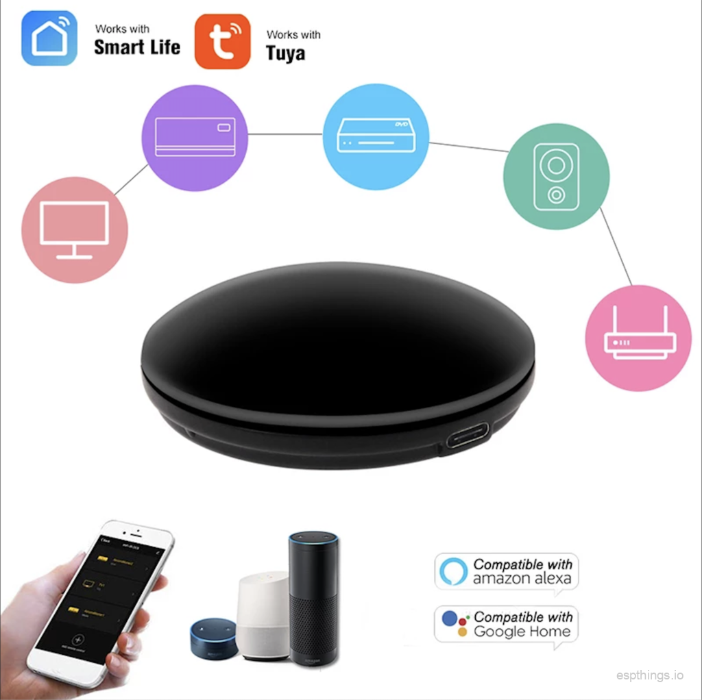
This time we put esphome on a Tuya Smart IR Remote Control WiFi IR Blaster which we bought from Aliexpress seller ‘FrankEver‘.

It’s just a cheap IR blaster that runs Tuya cloud software which potentially exposes all your data to the Chinese government. Not something we particularly like 😛
When using esphome software on this ‘thing’ it transforms into a powerful locally controlled IR gateway for use with Home Assistant. You can control your TV, Airconditioning, Radio and so on…. all directly from Home Assistant. without any cloud interference 😉
What do You need for the ‘operation’?
- A few dupont wires (male to female)
- A Soldering iron. More about soldering here
- A small Phillips-head screwdriver, or get a fantastic set here: Aliexpress
- A USB to UART TTL Module (choose: CP2102 5PIN)
- Nerves 😉
So let’s begin and put a screwdriver to the thing!
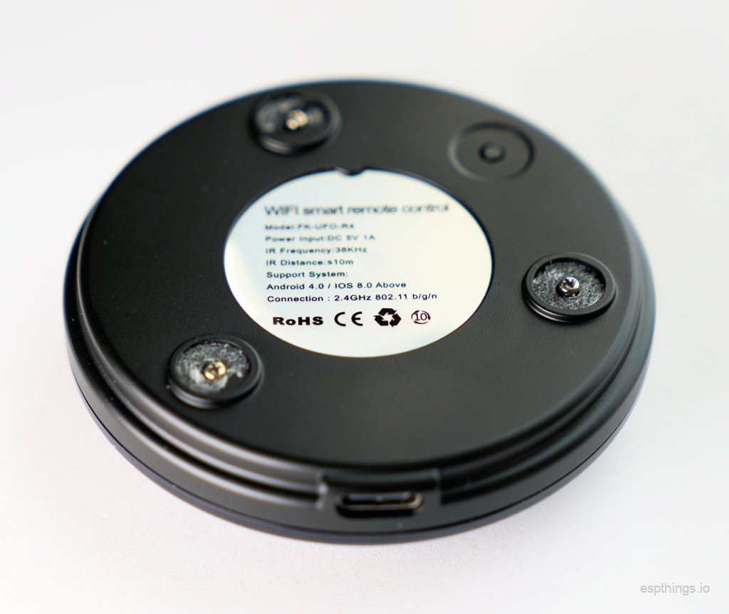
- On the bottom, carefully remove the 3 rubber feet and put them somewhere safe. You need to stick those back!

- Using a small “watchmaker screwdriver” remove the 3 tiny phillips-head screws. If you do not have such a screwdriver, consider this excellent set from Aliexpress
- Remove the PCB.
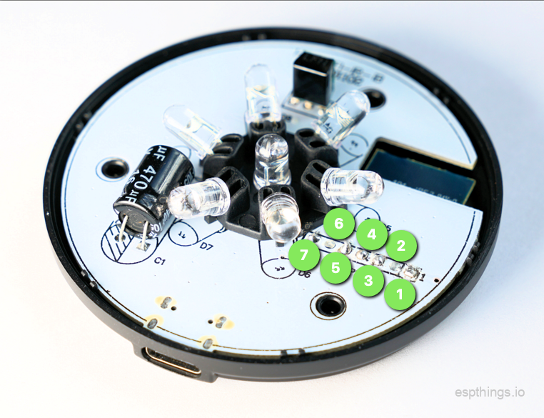
- Solder 3 dupont wires on the PCB on position 4 (RX), 5 (TX) and 7 (3,3v). Just solder the male side of the wire on there using a low temperature (350 degrees or so). These need to be removed later. If you do not have any dupont wires, buy some here.

- Take 2 dupont wires. Cut one in half. Use the half with the male pin and strip the shielding off on the other side of the wire. On the other dupot-wire, remove some shielding halfway the wire. Twist them together and solder the twisted copper connection. It will now look like this:

- Solder one male pin to position 1 (GND) and the other male pin to position 3 (IO0) on the PCB.
- Connect the USB to UART TTL Module to the corresponding pins.
1+3 > GND (To put the esp in flash-mode)
4 > RX
5 > TX
7 > 3,3v (be careful not to connect to 5v on the USB to UART TTL Module side!) - Use esphome flasher to upload the esphome binary (refer to he config below). Check if the the firmware flashing was successful.
- Remove the USB to UART TTL Module and carefully desolder all 5 wires and test boot the IR-blaster.
- If all works OK, put the thing back together and enjoy!
The example below controls a Daikin Climate unit, but You can virtually control any IR device. Read the instructions on the esphome website!
substitutions:
  devicename: esp_ir_01
  upper_devicename: ESP IR - 01"

esphome:
  name: ${devicename}
  platform: ESP8266
  board: esp01_1m

wifi:
  ssid: !secret esphome_wifi_ssid
  password: !secret esphome_wifi_password
  power_save_mode: high
  ap:
    ssid: $devicename
    password: !secret esphome_ap_password

captive_portal:

api:
  password: !secret esphome_api_password

ota:
  password: !secret esphome_ota_password

logger:

web_server:
  port: 80

# GPIO	Component	Description
# 04	LED1i (52)	Blue LED - Link status
# 05	IRrecv (51)	IR Receiver
# 13	Button1 (17)	Button
# 14	IRsend (8)	IR Transmitter

remote_transmitter:
  pin: GPIO14
  carrier_duty_percent: 30%

remote_receiver:
  id: rcvr
  pin:
    number: GPIO5
    inverted: True
  tolerance: 55%
  dump: all

climate:
  - platform: daikin
    name: "$upper_devicename Living AC"
    receiver_id: rcvr

binary_sensor:
  - platform: gpio
    pin:
      number: GPIO13
      mode: INPUT_PULLUP
      inverted: true
    name: "button"
    on_press:
      - logger.log: "$upper_devicename button pressed"

output:
  - platform: esp8266_pwm
    id: esphome_ir1_led
    pin:
      number: GPIO4
      inverted: false

light:
  - platform: monochromatic
    name: "$upper_devicename Blue LED"
    output: esphome_ir1_led
    id: light_led
If you have any issues, just put them in the comments.
We buy all this stuff out of our own pockets. If you would like to support us, please consider using our affiliate links to buy your parts and tools. This does not cost you a penny more, but we get a very small fee that helps us finance this website.
Make sure to subscribe to our (still pretty empty) YouTube channel so you won’t miss any of our upcoming project videos!
Please subscribe to our newsletter!

Hi,
The Tuya remote control blasters I received yesterday didn’t have an ESP inside, but the WB3s which is incompatible with ESPhome. I replaced the WB3s by an ESP-12E but couldn’t flash it with the pinouts in the desciption. It turns out they changed the pins for J1 as follows:
1 – 3.3v
2 – RST
3 – TX on the CHIP – RX to the UART TTL module
4 – RX on the CHIP – TX to the UART TTL module
5 – GPIO0, that needs grounding to put the chip in flashing mode
7 – GND
Next to that, they left GPIO15 floating, apparently not used for the WB3s, but necessary for the ESP. Connect it to the GND pin with a small wire.
With this brainsurgery and changes to the pinout, the blaster comes to live and can be used with the exact same esphome yaml as above.
If you need to replace an WB3s as well, make sure to be gentle with a soldering iron as the PCB pads are thin. Best to use a hotair station.
Enjoy!
Hi Jeroen,
Thanks for that update. A lot of ‘Tuya’ manufacturers are sadly switching to different (mostly Realtek based) chips, but you are the first to report frankever now also revised these IR blasters. 🙁
Kind regards,
Michel
Any alternative shop where i can buy this device with esp8266 chip?
I tested replacing the brains with an ESP-12E on the latest tuya blaster being sold on aliexpress. Desoldering was not a smooth process. If someone knows a better way than a hot air station, please let me know! I think the hardest part is there’s a large pad on the underside of the board.
They no longer provide access to all the pins for programming on the board. I ended up following a guide to flash directly to the ESPusing some resistors and capacitor which went smoothly. When testing the functionality, I could turn the LED on and off, the push button would register, but the receiver didn’t seem to work, at least nothing showed up in the logs. Maybe I did something wrong, but things were looking good. Anyway, desoldered the wires I had directly soldered onto the ESP and the blaster won’t turn on anymore. Not sure if it’s worth trying again on another board or just buying some LEDs and make something from scratch.
Hi, Thanks for the write up. The methods that you have mentioned above still holds good for the IR blaster that comes with TYWE3S as well. This includes header connection as well as the YAML configuration that you have given. For flashing I have used https://web.esphome.io/ which is web based, does not require any tool to be downloaded. The link will not work on Firefox, it is good with Chrome.