Athom Mini Relay Switch for ESPhome
In this article we cover the Athom Mini Relay switch, a fairly small Relay switch for use behind your existing wall switch. These kind of switches are sold by manny companies, mainly based on Tuya firmware for use in a Chinese cloud, which we are not particularly a fan off, for obvious reasons. 😉
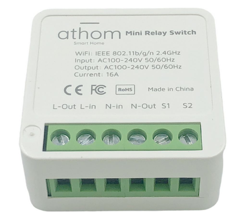
So what makes this one special? Well Athom sells their products with open source based firmware on them. They sell products with Tasmota, ESPhome, WLED and Homekit compatible firmware. The switch itself is really nothing special, as these switches are even sold in the same enclosure for the Tuya platform. The Tuya version does NOT contain a ESP8285, but the Tuya WE2S, which is not compatible with Tasmota or ESPhome!
Table of Contents
Hardware
When we open the small 4x4x2cm enclosure we find a ESP8285 based module, A 16A 250V AC Relay, squeezed on a ‘OK-ish’ PCB. It’s pretty much in line with all the other switches we tested. I will not rely on the Relay actually being capable of switching 16A and I would advise you to do the same.
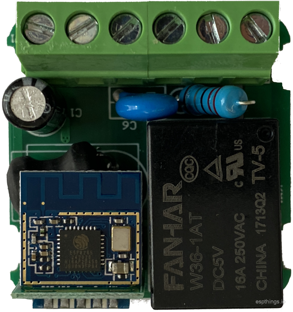
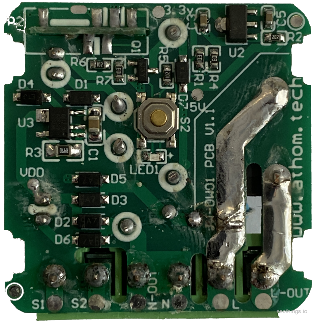
In my case this switch had a rather unwanted ‘feature’ were the screw terminal was soldered the wrong way around. In the picture below you’ll find the Tuya based version on the left and the Athom version on the right.
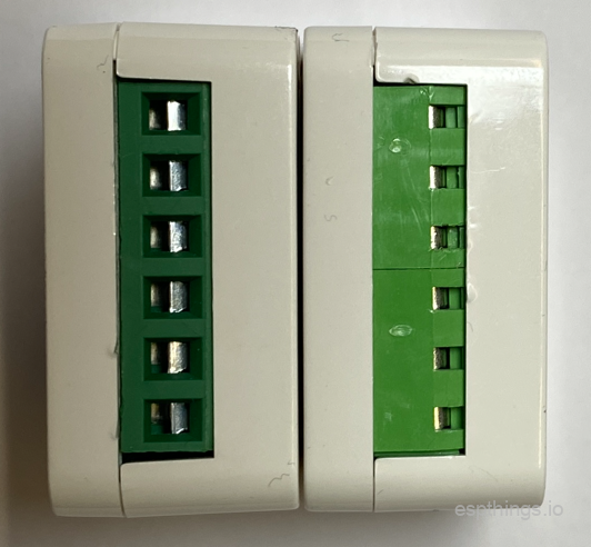
We contacted Athom about this, and the issue was very quickly investigated. They found no other modules where the terminals where soldered the wrong way around,. They ensured us that Quality Assessment would change from testing on top of the terminals to testing at the back of the terminals, which will prevent any more mistakes from happening. Many other manufacturers didn’t even bother to reply to quality issues we brought before them, so kudo’s to Athom!
Price
We purchased both the Tuya version as well as the Athom version of the Mini Relay Switch out of our own pocket on Aliexpress. The Athom version is somewhat more expensive both in unit price as well as shipping cost. Is the somewhat higher price worth it then? I my opinion it’s more then worth it. Most Tuya based devices are no longer sold with ESP8266 or ESP8285 MCU’s inside, which makes it impossible to flash an alternate firmware, but even if you still could, I would not advice you should. Soldering wires to theses devices temporarily for flashing another firmware can be a real pain and costs a lot of your time.
Use cases
So what could we use this switch for? Well, you could hide it behind your wall switch to control the light in your hallway, garage, staircase. As there is only one relay, which I would advise not to use with a higher load then 10A (2300Watt/230V or 1100Watt/110V), switching off and on light seems to be the most obvious use case, but you can utilize the switch to control other devices.

Using the relay with 1 switch

Using the relay with 2 switches
Firmware (ESPhome)
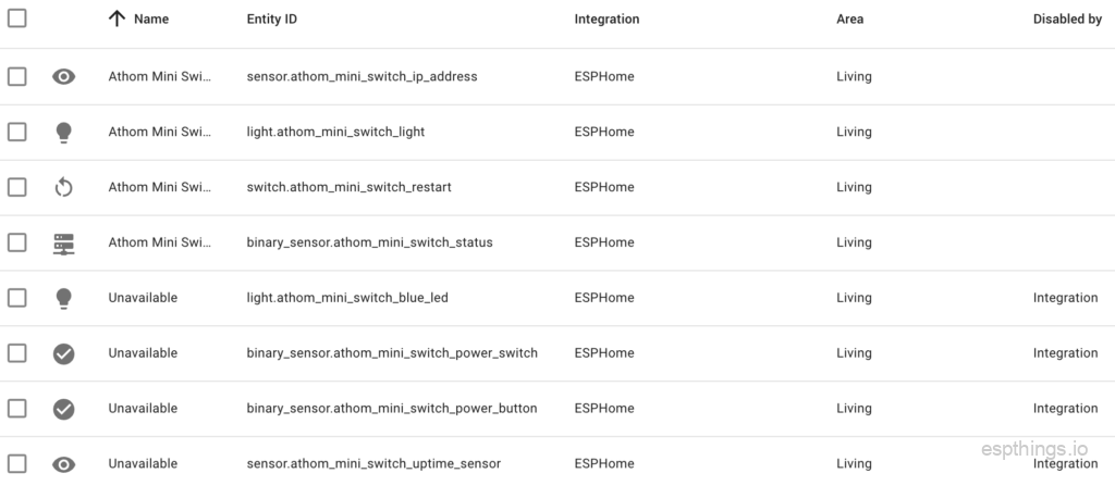
When connection the module to AC power, it presents a Wifi Access-point with the devices name and a mac-address suffix. Just connect your computer to this Wifi network and enter your own Wifi Credentials when prompted.
The switch will now be auto-discovered by Home Assistant. Click on the notification and follow the instructions. That’s it!
Configuration
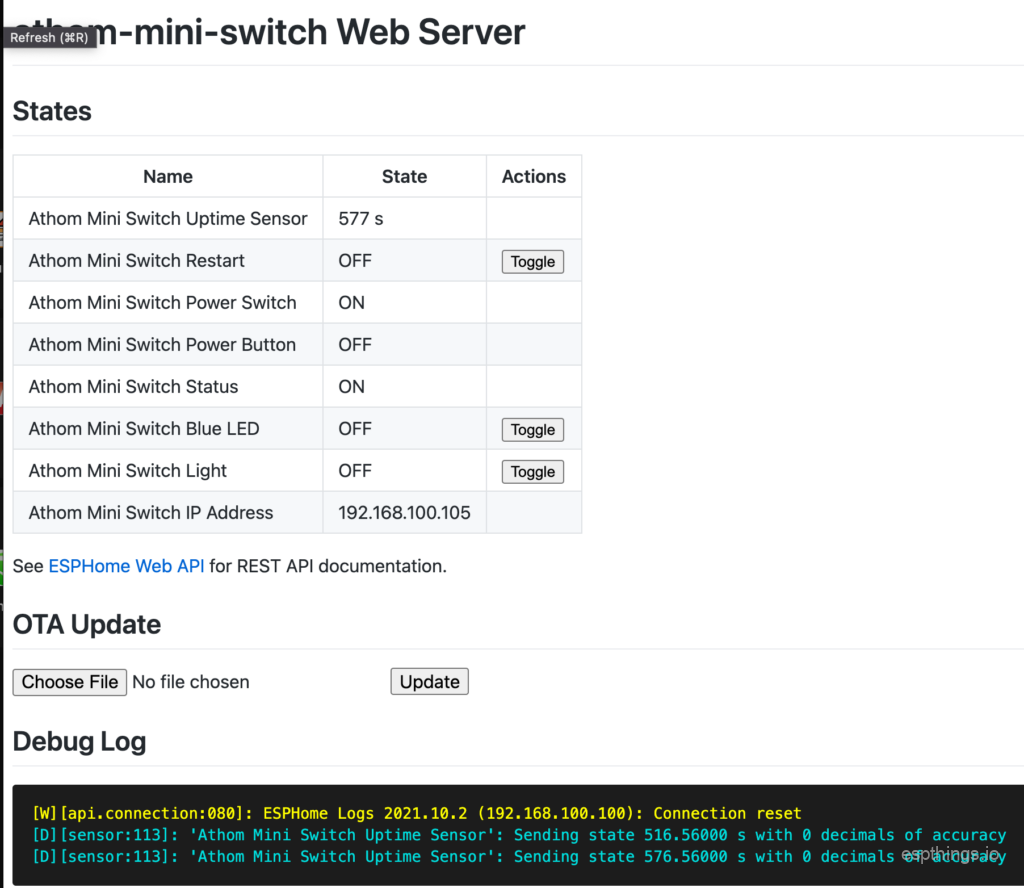
You can also opt to create your own ESPhome configuration or update the device. Athom has put a ESPhome configuration file on GitHub for every single device they sell. This configurations are put together quit well and are a good starting point. Create your own config and just upload it to the web-ui of the device:
Final thoughts
We have used the Athom Mini Relay intensively for 2 weeks now and it still works great and reliable. For the money you pay for this thing, you really can’t go wrong!
If you enjoy our designs, reviews and news articles, please leave a comment and subscribe to our youtube channel, to help us grow the website and channel!
Please subscribe to our newsletter!
hi, did you figure out how to connect it to the light switch on the wall that has NO neutral wire? or impossible?
Also, for the 2 switch configuration (like 1st switch on the ground floor and 2nd floor – both are turning on/off the light on the stairs) – I am asking as the example shown on Athom web (and yours) is not the way the 2 switches are connected usually – here in UK the common pin is connected between 2 switches – as per the diagram above, there is no way to connect it)
thx
This switch requires to operate a phase (L) and neutral (N). The power supply in the switch draws too much power to do it differently….
The red wire between the switches in the 2nd diagram should be black. That is the standard way, at least in the Netherlands, to connect the switches. Safety is the reason behind this. If each switch gets a phase and neutral, and the common (change over contact) is connected to the light fitting, it will work too, but there is a 50% chance that the outer ring of a lightbulb (Either the E14/E27 version or any other type of light fitting where the outer ring is a conductor) is connected to the phase…. The diagram shown will always apply the phase to the center of the socket, which is impossible to touch when a bulb is screwed into the socket.