4 channel Digital LED controller – ET-DL01
Table of Contents
Introduction
Our previous design, the ET-AL01 Analog LED controller, was designed to control the regular “Analog” (RGB) LED strips. These strips are easy in use, but due to the way they work, the whole strip will emit the same color.
There are RGB LED strips available which have RGB LEDs installed which can be addressed individually, the so-called “Neopixel” strips. These strips are based on LEDs which use a WS2812 or compatible interface chip, which allow each LED to have a different setting / color. There are even addressable RGBW and WW/CW addressable LED strips available. More on that later.

Please subscribe to our YouTube channel and hit the bell to never miss a (esp)thing!
Design parameters
The requirements were:
- ESP32 or ESP8266 controlled. Preferably ESP32, which allows more LEDs to be controlled at a fast rate
- Operating at 5, 12 or 24V DC, so the LED power supply could also feed the controller
- Four output channels
- Two input channels for sensors
- One universal IO
- Serial interface
- Must fit in a nice looking enclosure, should not look too industrial
- Parts should be available at AliExpress or Amazon for affordable prices, making it as cheap as possible to build
- Firmware should be ESPhome or WLED. (Something which is achieved by using the ESP32 / ESP8266 modules)
Practical design
The LED strips are normally based on a WS2812 or compatible controller chip. A table showing the electrical characteristics is below:

As you can see the Vdd, or the power supply, of the chip is normally between 4.5V and 5.5V, and the logic levels to drive the chips are related to the Vdd. A logic “1” is defined as “0.7 Vdd”, which means that when the chip is powered by 5V, the logic “1” level is 0.7 x 5.0V = 3.5V. The logic “0” level is defined as 0.3 Vdd, which results in 1.5V.
These levels indicate that a voltage less than 1.5V is interpreted as a logic “0” and a voltage greater than 3.5V is interpreted as a logic “1”.
Since the ESP8266 or ESP32 controllers are using 3.3V as IO voltage, which is not sufficient as per the datasheet to reliably generate logic “1” voltages, some sort of interfacing needs to be created.
Level shifter
As indicated above, there needs to be a reliable way to generate the correct voltage levels to drive the LED controller chip. In our previous design we had a similar issue, not to drive a chip, but to drive the MOSFETs at a higher voltage. We can use exactly the same solution, the 74HCT244 chip, for this Digital LED Controller. For a complete explanation why this chip is suitable, please read the section in the ET-AL01 blogpost.
See below for the signal coming from the ESP32 to the 74HCT244:

This is the output from the 74HCT244 to the LED strip:
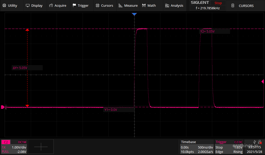
Output frequency: (Measured with one channel in use, running the “Rainbow mega fast” effect.)
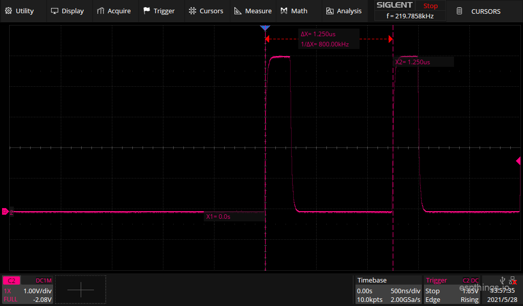
As you can see the pulses are sent out with a frequency of 800kHz.
Power supply
The LED strips come in several different power supply versions. The most common supply voltage is 12V, but 24V strips and 5V strips are also available. To be able to feed the ET-DL01 controller from the same power supply as the strips it is driving, the design has incorporated a voltage regulator which allows input voltages of 8 – 24V. If 5V strips are being used, the voltage regulator needs to be bypassed, for which a simple solution has been created. At all times, the IO voltage to the LED strips will be 5V!

When the power supply is 5V, do not install the diode D1 and voltage regulator IC1. Instead place a jumper as indicated on the PCB. This will remove the reverse polarity protection, so please take extra care when connecting the power supply to the controller! Since there is no voltage regulator, please make sure the voltage does not exceed 5V!
Outputs
The controller has a total of 4 outputs for the LED strips. These outputs are exposed on the terminal strip, and are referenced to the GND (negative) connection of the power supply. To make sure that the LED strips work reliably, it is very important that the GND (negative) connection of the data connection is properly at the power supply. It is recommended to keep the wiring between the controller and the LED strips as short as possible!
Inputs
The controller has 2 inputs for switches or sensors. To activate the inputs, a voltage of 3.3V or 5V needs to be applied. For this reason a 5V connection is made available on the terminal strip, which can be used to power sensors etc. Both inputs are isolated from the controllers by an optocoupler. The optocoupler protects the inputs of the ESP module against damaging voltages, which can be picked up by long wiring to the input switches or (faulty) sensors.
Additional IOs
Besides the dedicated inputs and outputs, the controller has one additional IO pin exposed. This pin is directly connected to the controller, and can be configured as input or output by the YAML configuration file. Since it is directly connected, take care in using this pin, since it is possible to damage the ESP controller easily!
Lastly, the serial port of the ESP module has been made available. This serial port uses 3.3V signal levels. “TXo” means transmit out, data from the ESP module to the outside world, “RXi” means receive data from the outside world to the ESP module. Be careful not to exceed the 3.3V voltage levels, since this might damage the module permanently.
Circuit diagram and PCB
The diagram:

The PCB:
Build it!
Bill of materials
See below the list with the components you will need to build the DL01 controller. A number of these items will not be sold in smaller quantities at AliExpress. We will try to use the same components as much as possible in future projects.
We would really appreciate it if you will use the links below to buy the components, since it will give a little bit of commission to us without any additional cost for yourself. These commissions will be used to cover some of the costs involved in the development of the design.
| Reference | Qty | Description | Link |
| WEMOS1 | 1 | Wemos Mini D1 ESP32* | AliExpress |
| WEMOS1 | Wemos Mini D1 ESP8266* | AliExpress | |
| IC1 | 1 | Switching regulator 8-32V in, 5V out | AliExpress |
| IC2 | 1 | 74HCT244 | AliExpress |
| OK1, OK2 | 2 | PC817 / EL817 Optocoupler | AliExpress |
| D1 | 1 | 1N4001 | AliExpress |
| C1 | 1 | 470µF / 16V 6mm diameter, 2.54mm pitch | AliExpress |
| C2 | 1 | 0.1µF – pitch 5.08mm | AliExpress |
| R1, R2 | 2 | Resistor 220 ohm | AliExpress |
| X1 | 1 | 9 pole terminal, or 3x 2 pole + 1x 3 pole. 5.00mm pitch | AliExpress |
| JP1, JP2 | Male pin headers. 2.54mm pitch | AliExpress | |
| Enclosure | 1 | 76x56x29mm (AK-N-04) | AliExpress |
| PCB | 1 | A 5-pack is the smallest order at PCBway, enough for you and your friends 😉 | PCBway |
| LED strip | opt. | 12v WS2811 RGB strip | AliExpress |
| LED strip | opt. | 12V SK6812 RGBW strip | AliExpress |
| Power Supply | opt. | SANPU SMPS LED Driver 110v/220v 12v 150w | AliExpress |
* You only require one of the modules!
Putting it together
Like with all other projects, it is the easiest to start with identifying the components purchased as discussed in the blog post. After sorting the components and cleaning the PCB, start with the lowest components first. For this project, we advise to work in this order:
- Resistors
- Diode
- 74HCT244
- Optocouplers
- Pin headers
- Screw terminals
- ESP module headers (Use the hints in the soldering blog post!)
- Electrolytic capacitor
- Voltage regulator. Make sure that the voltage regulator is not too tall for the enclosure. You can reduce the height by either by bending the pins of the voltage regulator a little bit, or mounting the regulator horizontally, so it hovers above the 74HCT244.
Once all components are soldered in place, perform a good visual check of all joints, and pay particular attention to possible solder bridges (unwanted solder connections between pins). Do not forget to clean the excess solder flux from the PCB using alcohol!
Software configuration
substitutions:
  devicename: et-dl01
  long_devicename: ET-DL01 Digital LED controller

esphome:
  name: $devicename
  platform: ESP32
  board: mhetesp32minikit

wifi:
  ssid: "esphome"
  password: "Qwe123456"
  ap:
    ssid: "$devicename Fallback Hotspot"
    password: "yourpass"

captive_portal:

logger:

api:
  password: "yourpass"

ota:
  password: "yourpass"

sensor:
  - platform: wifi_signal
    name: "WiFi Signal $devicename"
    update_interval: 60s

light:
  - platform: fastled_clockless
    chipset: ws2812b
    pin: GPIO22
    num_leds: 100
    rgb_order: BRG
    name: "$long_devicename channel 1"
  - platform: fastled_clockless
    chipset: ws2812b
    pin: GPIO26
    num_leds: 100
    rgb_order: BRG
    name: "$long_devicename channel 2"
    effects:
      - addressable_rainbow:
      - addressable_rainbow:
          name: Rainbow Effect With Custom Values
          speed: 10
          width: 50
      - addressable_rainbow:
          name: Rainbow mega fast
          speed: 35
          width: 200
      - addressable_scan:
      - addressable_scan:
          name: Scan Effect With Custom Values
          move_interval: 80ms
          scan_width: 1
      - addressable_twinkle:
      - addressable_fireworks:
      - addressable_color_wipe:
Connection
Main wiring
Under normal circumstances the DL01 will be fed by the same power supply as the LED strip. Since the LED strip can draw a significant amount of current, it is advisable to connect the DL01 in the following manner: (We use a 12V power supply and 12V strip as an example)

As you can see, a separate negative (GND) wire runs from the DL01 module to the negative of the power supply. The positive connection can be “shared” with the strip, since the module contains a regulator which will filter out the voltage dips and spikes due to the change of current to the LED strip.
The “Din” connection of the strip is connected to the “CH1”, “CH2”, “CH3” or “CH4” terminal.
For the power wiring, do not use very small wires, since this will create issues with the higher currents to the LED strip. For the data connection you can use small wire, since there is a very small current flowing through the wire.
Sensor wiring
In case you would like to connect a sensor or switch to the DL01, you can do this as per below example. We show here the connection to a PIR motion detector. The PIR module runs at 5V, which is available on the terminal strip:

Since the currents are small, you can use small wire for this. The inputs are 5V tolerant, so there is no worry about blowing up the module.
ESP32 or ESP8266?
For this project, like with the AL01, you can use the ESP8266 or the ESP32 based modules. The difference between the modules is mainly the processor speed, which determines the max. number of LEDs which can be controlled at a higher refresh rate. For smaller (less LEDs) systems, an ESP8266 based module will work fine. However the moment the number of LEDs in the system becomes too large, there is a chance that the LEDs will start to react visibly slower. Therefore we recommend using an ESP32 based module, unless the number of LEDs is very limited.
Final thoughts
During the construction of the prototype, and the measuring of the signal waveforms afterwards, we found out that a bad batch of the 74HCT244 were delivered. The output voltage never reached the expected 5.0V, but did not go over 3.6V. The LED strip did work with this signal though, but if this 74HCT244 batch would have been used for the AL01 analog dimmer, the MOSFETs on that module would not be driven correctly, resulting in a lower light output. We did a test, and instead of the expected 12V output, only 7V output was achieved on the AL01 dimmer.
If you run into issues during the construction, or you have any question regarding this controller, please leave a comment below. We will try to reply as soon as possible!
Make sure to subscribe to our YouTube channel so you won’t miss any of our upcoming project videos!
Please subscribe to our newsletter!

Hello there;
(IC1 – Switching regulator 8-32V in, 5V out)
What else can I use instead of this product? I ordered the PCB, but I am having difficulty in obtaining this product.
Hi Why is that? The link works: https://www.espthings.io/index.php/recommends/ali-switching-regulator-6_5-40v-in-5v-out/
I was having problems with customs and cargo in Turkey, luckily I found it elsewhere, thanks bro.
WS2815 How should I connect this LED with 4 pin connection to the pcb?
Thank you, master. I have a last question, I will do all the lighting in my house with these leds, but since I can’t supply the products in Turkey, I can’t do trial and error. If you have information, I would be very grateful if you could enlighten us. In Neo Pixel led strips, which of the following products can I get the brightest white light, especially?
1. SK6812 RGBCW 1m 60 Led – https://tr.aliexpress.com/item/32476317187.html
2. WS2811 RGB 1m 60 Led – https://tr.aliexpress.com/item/32961181562.html
3. WS2815 1m 60 Led – https://tr.aliexpress.com/item/32961181562.html
No.1 will give you the brightest white light in my opinion.
thanks bro
You can also connect BI to DI, so you have redundancy in the line…. If one LED fails on the dataline, the backup line will take over, and the strip will continue to operate.
Hi;
I am having such a problem. I connected a WEMOS ESP8266 module to the PCB. I set it to be CH1=D1, CH2=D0, CH3=D5, CH4=D6 via the esphome. CH1,CH3 and CH4 work fine, but I can’t get results from CH2. Can you help me how can I detect the problem?
How did you do that? Can you post a picture?
You can find the pictures at the link below.
https://resimyukle.io/g/Bk7Njme7MM
I’m unable to view those pictures
where can i download it so you can see it
the link to the pcb in pcbway points to the analog version.
Thank you. I have just corrected the issue
pcbway has taken over 60 days to deliver, so i’ve built the circuit on a breadboard.
i’ve got three strings of 5m/30/sk6812 from BTF and they all do the same thing.
i was wondering if you might have any suggestions:
only 113 of the 150 will light.
the colours are pretty random. i’ve tried every chipset in the yaml file and they all seem to do pretty much the same. white will show up as white, but anything else is pretty random. usually white/green, then blue and then red in a repeating string.
any suggestions would be much appreciated.
it appears to be an issue with the fastled_clockless library.
for anyone trying to get this to work, the following might be of some use:
light:
– platform: neopixelbus
variant: SK6812
pin: GPIO22
num_leds: 150
type: GRBW
name: “${device_description} channel 1”
effects:
– addressable_rainbow
– addressable_color_wipe
– addressable_scan
– addressable_twinkle
– addressable_fireworks
– addressable_random_twinkle
I never had issues with fastled_clockless. What esphome version where you running?
I am running ESPHome (2021.12.1).
I will try again with fastled_clockless.
I was using my breadboard build and maybe there are some issues with that.
60 days? That’s a long time. I never waited that long for a package from PCBway.
they finally arrived after about 65 days. nice boards!
If and when you do an iteration of the board design you might add a couple of pin headers so the board can be programmed in place (IO0 to ground). This is only needed the first time the board if flashed with esphome.
Also, perhaps you could extend the rows of holes (TD0, SD), TCK and SD3) so that the supplied headers for the D1 MINI can be used.
High speed signals on a not-high quality breadboard can be very tricky. Remember that the data lines are at a relative high clock frequency, which will create / require steep edges. This requires decent power line decoupling, as close to the 74HCT244 as possible. (That is the function of the 0.1µF ceramic capacitor. It is a critical component!) Make sure that your 74HCT244 is really switching to 5V, and not to a (much) lower voltage. You can measure that in a static condition on your breadboard. Just apply 3.3V to an input of the buffer, and the output should switch to 5V.
For those (like recent me) who do not understand this: when Paul talks about requiring “steep edges”, he’s referring to the difference between “voltage up” (aka on) and “voltage down” (aka off). While I thought that “PWM turns off and on X times per minute” meant that it’s a perfect binary with only On and Off as possible states, the truth is that there is *always* a slope between on and off (or off and on). Even inside the fastest CPU the signal ramps from 0V to some threshold that the next component counts as “up”. Sacrificing the quality of your electrical path (say by using a breadboard) can make this slope wider and sloppier and throw off everything else. There’s a great video from Linus Tech Tips called “This Just Saved me $100,000 – Totalphase Cable Tester” that explains this to someone who identifies with “I’m a technical person, but thought that binary signals were a simple on/off”
Could you advise which pins to use in combination with a wemos D1 mini esp8266 loaded with WLED?
Looking at the Circuit diagram and PCB i think it would be
ch0=D1=gpio5
ch1=D0=gpio16
ch2=D5=gpio14
ch3=D6=gpio12
Thanks
Thanks for this
After a couple months of waiting for parts I just built one with the ESP32mini and a 12V LED strip and it works perfectly.
Just copy-pasted the code above which was a nice bonus!
Can you share the Gerber files
No, sorry we do not share gerber files as those are often commercially exploited in some way.
Hello. Thanks again for another neat and useful project. I’ve already build the analog one and love it. One thing I would add on the safety part… some fuse socket on the power input/output
You can always use an inline fuse. Putting it in this design will make things significantly bigger, thus not fitting in the chosen enclosure.
When you say : “ keep the wiring between the controller and the LED strips as short as possible” how much can I push that distance ? I have a situation where I will use two channels for two 1.8 meter long strips and one of the strips will be at about 2 meters away from the controller … will it be ok?
Yes, with proper wiring that will be totally fine.
You say, remove the diode if we use 5v as power supply but that diode should help not burn stuff if polarity is reversed?
Hi Guy’s,
I have a System-Air PrioSil 200EC fan that I’d like to control wirelessly. It requires a input voltage of 0-10v for controlling the fan speed.
Would either this project or the Analogue controller be of any use for this?
You can’t use PWM for that with this module. What you need is: https://aliexpress.com/item/1005002698537337.html (PWM to voltage) and hook it up with a esp8266. Then use the PWM component to regulate 0-10 volt. We can not give you any further advise in this comment as this relates to the ET-Al01 and is a little off-topic.