5 channel Analog LED controller – ET-AL01
Table of Contents
Introduction
Michel asked me to design an analog LED controller with 5 channels, since he wanted to be able to control a nice LED strip with an RGB LED and a warm white and cool white LED (Like Philips Hue). When searching the internet he could only find controllers with a single channel, four channels or ten channels. But a 5 channel controller for these kind of LED strips was simply not available!
He was very specific in his request, so I wrote down some design parameters first.
Also check out our YouTube video, subscribe, hit the bell and send the link to all your friends. You know the drill 😉

Please subscribe to our YouTube channel and hit the bell to never miss a (esp)thing!
Design parameters
The requirements were:
- ESP32 or ESP8266 controlled. Preferably ESP32, due to the higher PWM frequencies the ESP32 supports
- Operating at 12 or 24V DC, so the LED power supply could also feed the controller
- Five channels, with an as high as possible current capability
- Must fit in a nice looking enclosure, should not look too industrial
- Parts should be available at AliExpress at affordable prices, making it as cheap as possible to build
- Firmware should be ESPhome. (Something which is achieved by using the ESP32 / ESP8266 modules)
Practical design
The heart of the design is a “Wemos Mini” (compatible) module. By using these modules, it becomes very easy to integrate, and greatly simplifies the design. It also allows people to pick an ESP32 or ESP8266 module, which creates a little bit of flexibility too.
To control the output channels, MOSFETs will be used, with a standard footprint / case so that a number of compatible models can be applied. The design is flexible enough to drive most of them.
Why use a 74HCT244 chip?
Since the ESP modules use I/O levels of 3.3V, and a lot of MOSFETs require more control voltage, a so-called “level shifter” needs to be used. Many different solutions exist, ranging from the usage of driving transistors, special level shift chips, or the usage of TTL chips. All solutions have pros and cons, and the decision has been made to use a TTL chip in this design. The decision was based on the easy (cheap) availability on AliExpress, very standardized operating parameters (irrespective of manufacturers!) and small footprint on the PCB.
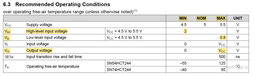
The 74244 exists in a number of TTL families, all with their own parameters. When looking at the requirements of the design of the controller, the most suitable family is the “HCT” family. See the below table from the datasheet of Texas Instruments SN74HCT244:
See the below table for the IO levels of the ESP32:

If you compare the two tables you see that the output level of the ESP chips are defined as a factor of “VDD”. VDD is for the modules used 3.3V, so if we convert the levels listed to fixed numbers, we see that the “High-level output voltage” has a minimum of 2.64V, and for the “Low-level output voltage” a maximum of 0.33V.
When the input levels of the 74HCT244 datasheet are checked, we see that the max. “Low-level input voltage” is defined as 0.8V. Therefore the 0.33V is low enough to ensure that the level is detected properly. Same for the min. “High-level input voltage” which is defined as 2V. The 2.64V from the ESP32 is therefore more than enough to ensure the logic “1” is detected properly.
In the table you can also see the output voltage specification. There are only two levels given, “Min” and “Max”. The “Nom” (nominal) is missing, since the output will only take 2 possible levels, which are defined as 0V and “Vcc”. The “Vcc” in the circuit will be 5V, therefore the output voltage for a logical “1” will be 5V. This is very beneficial for the driving of the MOSFET connected to the output pin.
The last parameter which is important is the max. output current per pin:

The 74HCT244 can supply max. 35mA continuously per pin. This is important to drive the gate of the MOSFET sufficiently in a rapid manner. The gate – source connection of a MOSFET acts like a capacitor, which needs to be charged for the resistance between the drain and source to lower. If the current flowing into the gate is limited / low, this charging will be slow(er). The HCT series has one of the highest maximum output currents. The opposite for the “switching off” of the MOSFET, the capacitor needs to be discharged. A lower discharge current capability will result in slower switching.
For a more in-depth discussion regarding the design, read this blog post.
Circuit diagram and PCB
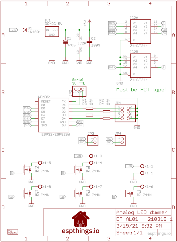
The design I came up with is this:
The PCB design of this diagram:

On top you see the GPIO interface pins. These can be used as a general purpose IOs. The number between ( ) are the IO numbers of the ESP32 modules, and the numbers between the [ ] are the IO numbers of the ESP8266 modules. You will need these numbers to configure the IOs in the software configuration. These pins are capable of handling 3.3V and 5V input levels, and if used as an output, 3.3V output level. To feed possible sensors, right next to the GPIO pins you will see the 5V and 3.3V power output connections. The 3.3V power is coming from the ESP module, and is limited in power. Try to limit the amount of current drawn from the pin (Think in currents not exceeding about 100mA). If you need a lot more current at 3.3V level, use an external voltage regulator, connected to the 5V power output. This is fed by the regulator on the PCB, and would normally be able to supply 250mA or more, depending on the regulator used, to the pin.
Next to the GPIO pins, the serial port of the ESP module has been made available. This serial port uses 3.3V signal levels. “TXo” means transmit out, data from the ESP module to the outside world, “RXi” means receive data from the outside world to the ESP module. Be careful not to exceed the 3.3V voltage levels, since this might damage the module permanently.
At the bottom you see the screw terminals. The power input is located on the right hand side, and the LED strip will be connected to “CW, WW, R, G, B, +”
Build it!
Bill Of Materials
See below the list with the components you will need to build the AL01 controller. A number of these items will not be sold in smaller quantities at AliExpress. We will try to use the same components as much as possible in future projects.
We would really appreciate it if you will use the links below to buy the components, since it will give a little bit of commission to us without any additional cost for yourself. These commissions will be used to cover some of the costs involved in the development of the project design.
| Reference | Qty | Description | Link |
| WEMOS1 | 1 | Wemos Mini D1 ESP32* | AliExpress |
| WEMOS1 | Wemos Mini D1 ESP8266* | AliExpress | |
| IC1 | 1 | Switching regulator 8-32V in, 5V out | AliExpress |
| IC2 | 1 | 74HCT244 | AliExpress |
| T1, T2, T3, T4, T5 | 5 | IRLZ44N or compatible logic level MOSFET | AliExpress |
| D1 | 1 | 1N4001 | AliExpress |
| C1 | 1 | 470µF / 16V 6mm diameter, 2.54mm pitch | AliExpress |
| C2 | 1 | 0.1µF – pitch 5.08mm | AliExpress |
| R1, R2, R3, R4 | 4 | Resistor 1k | AliExpress |
| X1 | 1 | 8 pole terminal, or 4x 2 pole. 5.00mm pitch | AliExpress |
| JP1, JP2, JP3 | Male pin headers. 2.54mm pitch | AliExpress | |
| Enclosure | 1 | 76x56x29mm (AK-N-04) | AliExpress |
| PCB | 1 | A 5-pack is the smallest order at PCBway, so talk to your friends 😉 | PCBway |
| LED strip | opt. | 12v RGBCCT | AliExpress |
| LED strip | opt. | 24v RGBCCT | AliExpress |
| Power Supply | opt. | SANPU SMPS LED Driver 110v/220v 12v 150w | AliExpress |
| Power Supply | opt. | SANPU SMPS LED Driver 110v/220v 24v 150w | AliExpress |
* You only require one of the modules!
Putting it together
When building the project it is the easiest to start with identifying the components purchased as discussed in the blog post. After sorting the components and cleaning the PCB, start with the lowest components first. For this project, we advise to work in this order:
- Resistors
- Diode
- 74HCT244
- Pin headers
- Screw terminals
- ESP module headers (Use the hints in the soldering blog post!)
- Electrolytic capacitor
- MOSFETs
- Voltage regulator. Make sure that the voltage regulator is not taller than the MOSFETs! You can do this by bending the pins of the voltage regulator a little bit, so it will lean a little bit.
Once all components are soldered in place, perform a good visual check of all joints, and pay particular attention to possible solder bridges (unwanted solder connections between pins). Clean the excess solder flux from the PCB using alcohol!
Software configuration
Once everything is soldered together, it is time for the software configuration. Follow the instructions in our YouTube video. Configuration files below:
Secrets:
esphome_wifi_ssid: 'your_ssid'
esphome_wifi_password: 'your_wifi_password'
esphome_ap_password: 'your_ap_password'
esphome_api_password: 'your_api_password'
esphome_ota_password: 'your_ota_password'
ESP32:
substitutions:
  devicename: et-al01_esp32
  long_devicename: ET-Al01 Analog LED controller (ESP32)

esphome:
  name: $devicename
  platform: ESP32
  board: mhetesp32minikit

wifi:
  ssid: !secret esphome_wifi_ssid
  password: !secret esphome_wifi_password
  ap:
    ssid: "$devicename Fallback Hotspot"
    password: !secret esphome_ap_password

captive_portal:

logger:

api:
  password: !secret esphome_api_password

ota:
  password: !secret esphome_ota_password

sensor:
  - platform: wifi_signal
    name: "WiFi Signal $devicename"
    update_interval: 60s

output:
  - platform: ledc
    pin: 26
    frequency: 25000Hz
    id: ledc_cw
  - platform: ledc
    pin: 18
    frequency: 25000Hz
    id: ledc_ww
  - platform: ledc
    pin: 19
    frequency: 25000Hz
    id: ledc_r
  - platform: ledc
    pin: 23
    frequency: 25000Hz
    id: ledc_g
  - platform: ledc
    pin: 05
    frequency: 25000Hz
    id: ledc_b

light:
  - platform: rgbww
    name: "$long_devicename LED-strip"
    warm_white: ledc_ww
    cold_white: ledc_cw
    red: ledc_r
    green: ledc_g
    blue: ledc_b
    cold_white_color_temperature: 5000K
    warm_white_color_temperature: 3000K
ESP8266:
substitutions:
  devicename: et-al01_esp8266
  long_devicename: ET-Al01 Analog LED controller (ESP8266)

esphome:
  name: $devicename
  platform: ESP8266
  board: d1_mini

wifi:
  ssid: !secret esphome_wifi_ssid
  password: !secret esphome_wifi_password
  ap:
    ssid: "$devicename Fallback Hotspot"
    password: !secret esphome_ap_password

captive_portal:

logger:

api:
  password: !secret esphome_api_password

ota:
  password: !secret esphome_ota_password

sensor:
  - platform: wifi_signal
    name: "WiFi Signal $devicename"
    update_interval: 60s

output:
  - platform: esp8266_pwm
    pin: D0
    frequency: 100 Hz
    id: ledc_cw
  - platform: esp8266_pwm
    pin: D5
    frequency: 100 Hz
    id: ledc_ww
  - platform: esp8266_pwm
    pin: D6
    frequency: 100 Hz
    id: ledc_r
  - platform: esp8266_pwm
    pin: D7
    frequency: 100 Hz
    id: ledc_g
  - platform: esp8266_pwm
    pin: D8
    frequency: 100 Hz
    id: ledc_b

light:
  - platform: rgbww
    name: "$long_devicename LED-strip"
    warm_white: ledc_ww
    cold_white: ledc_cw
    red: ledc_r
    green: ledc_g
    blue: ledc_b
    cold_white_color_temperature: 5000K
    warm_white_color_temperature: 3000K
Using a channel as a digital output
If you do not require all the analog channels, there is an easy option to create a digital channel out of an unused analog channel. To do this, do not mount the MOSFET for the channel, but instead install a jumper from the top connection to the center connection of the MOSFET footprint. This will make a direct connection from the 74HCT244 output, to the screw terminal. Once this connection is made, the output can be used to drive a WS28XX (or compatible) LED strip. For the respective channel a YAML entry needs to be edited;
Light:
  - platform: fastled_clockless
    chipset: ws2811
    pin: GPIO5
    num_leds: 238
    max_refresh_rate: 8ms
    rgb_order: BRG
    name: "$long_devicename-DIGITAL"
    effects:
      - addressable_rainbow:
          name: Rainbow Effect With Custom Values
          speed: 10
          width: 50
      - addressable_rainbow:
          name: Rainbow mega fast
          speed: 35
          width: 200
      - addressable_scan:
          name: Scan Effect With Custom Values
          move_interval: 100ms
          scan_width: 1
      - addressable_color_wipe:
          name: Color Wipe Effect With Custom Values
          colors:
            - red: 100%
              green: 100%
              blue: 100%
              num_leds: 1
            - red: 0%
              green: 0%
              blue: 0%
              num_leds: 1
          add_led_interval: 100ms
          reverse: False
Final thoughts
After the design was finished, we both build a controller to test. The controller which Michel built has been in use for a number of weeks now, without any issue. No issues with MOSFETs getting warm or overheating, no issues with stability, so we are confident that this controller will work for you too.
This project, the ET-AL01 5 channel Analog LED controller, was the reason for starting this website. We found out that there are more circuits which we think people are looking for to build. What we decided to do is to create more projects with the same design philosophy; Easy to build, of easily and cheaply available components, and well tested. And they need to look nice too!
For us one of the major things is also to make sure that the projects / circuits we publish are safe to build by other people. We will do our utmost best to ensure this. However, like with all other DIY projects you will find online, we will not be responsible for any possible (financial) damage which might result from building our projects. Yes, unfortunately we need to include this disclaimer…
If you run into issues during the construction, or you have any question regarding this controller, please leave a comment below. We will try to reply as soon as possible!
Make sure to subscribe to our YouTube channel so you won’t miss any of our upcoming project videos!
Please subscribe to our newsletter!

[…] previous design, the ET-AL01 Analog LED controller, was designed to control the regular “Analog” (RGB) LED strips. […]
I have been looking for a product like this for a long time !
can they deliver the PCB to Germany?
Yes! They ship worldwide!
Have fun building it..!
Is it possible to order the pcb from an other shop? Pcbways charge 25$ only for the shipping to Germany it’s too much for me only for 1 pcb.
This is really good and I have been looking for a similar solution for a while now.
I have a couple of suggestions for the V2.0:
– An Ethernet port option for a wired connection to the server (may be something similar to “Lan8720 breakout”). Perhaps using a Board that supports PoE ?
– PIR sensor integration because why not!
– a binary_sensor ( a press button switch) to toggel the LED light locally using “Template Switch” function incase the connection with Home-Assistant server was lost for some reason
For general purpose, there are four gpio pins exposed, together with a power connection and ground. Check the top header on the PCB. Unfortunately there was no physical space to add screw terminals for these connections.
We will keep the suggestion of the Ethernet port / POE in mind. Maybe we’ll implement it in a future design.
Couldn’t find an analog 5 channel? What about the H801? https://esphome.io/cookbook/h801.html
That is indeed a 5 channel controller. I had 2 of them in my house, but it is esp8266 based and thus has software PWM with frequencies up to ‘only’ 1000Hz. The esp32 does hardware PWM up to 40Mhz.
I have mine running at 25.000Hz which makes a huge difference for video. If I now film from my office or make a teams call, there is no more flickering.
I also have the esp32 BLE enabled so when I am in the office some motion based automations are disabled using BLE presence detection.
The H801 also has no options for external sensors and no options for converting a analog channel to digital (addressable led).
Good answers! Perhaps I was fooled by your design parameters which included esp8266. Thanks for the great site.
Also https://quinled.info/quinled-an-penta-diy-specifications/
Greetings.
Just found your article, interesting idea already ordered my 5 PCBs 🙂
But as a ESPHome newbie I have a question: it is possible to I make ET-AL01 acknowledge a momentary switch, enabling physical power toggle, for example? I would be wonderful to control lightning through physical switch, leaving finetuning to the HA.
The short answer is Yes!
You can connect up to 4 buttons to the 4x GPIO spots on the bottom-right corner of the board (They are in pairs, with the GPIO pin right next to a ground pin). You can then use ESPHome to do any automation you like. I personally did ON/OFF, BRIGHTNESS UP, BRIGHTNESS DOWN, and toggling a single effect.
Hi, thanks for the design, I have built one and so far so good. I have a question though: what are the physical dimensions of the PCB, more specifically, what is the X and Y distance between the mounting holes? Thanks Ondrej
I don’t understand. If you build one, you have the measurments or not?
It would be more precise if you told me the dimensions instead of me measuring them from the physical PCB… That’s what I mean.
External: 70.0 x 50.0 mm
Holes: 61.8 x 40.9 mm
Hole diameter: 3.5 mm
Great project. So if I wanted to drive addressable LEDs (WS28XX (or compatible) LED strip) I don’t use the MOSFET. For a digital channel are the limits (i.e. max # LEDs per channel) driven by the MCU (ESP8266 vs ESP32) and the external power supply? What else I’d have to take into account?
If you are looking for a design only to drive the WS28XX LED strips, I would like to recommend the design we made for this: https://www.espthings.io/index.php/2021/08/15/4-channel-digital-led-controller-et-dl01/
To use one or more channels of this design for the WS28XX strips, make sure your power supply is sufficient, and that the cabling to the first LED of the strip is as short as possible. The data signals driving these strips use pretty high frequencies, and the timing is relatively critical. (See the comment section of the aforementioned post)
Looks great!
Are there Io unused? For i2c ina260 power measurement and a digital or analog input for internal temperature measurement?
BR
I’ve now had the boards for about a month and have successfully driven a wide variety of analog LEDs, but I have a couple concerns and would like some guidance:
Flickering! There are intermittent flickers while changing brightness, while being at a low brightness, and so-on. There is even flickering at full brightness. This is with 12V and 24V strips.
Off too early: The lights typically don’t light below <10% "brightness" in ESPHome. Is there a way to fix that or just mitigate it in ESPHome?
Thanks!
Can you please tell me which board you are using? Is it the esp8266 or the esp32? Intermittent flickering points to a CPU which is too busy to handle the pwm output in a timely manner….
The 10% brightness switch off you might be able to mitigate a little by changing the gamma_correct parameter of esphome.
Having an issue with WLED on the 8266:
It does not accept GPIO 6, 7, or 8 as PWM lights.
Any suggestions?
Nevermind, found the issue: the PCB lists the “D” labelling of the pins (D0, D5, etc), but these actually correspond to different GPIO pins.
D0 = GPIO16, for example.
WLED needs the GPIO number, not the “D” number.
Hi there, thanks for this! Before finding your website I had created my own PCB using an ESP32 for the same purpose of high speed PWM lighting that none of the prebuilt solutions seemed to have. I swear even 500hz looks visibly flickery to me, but maybe that’s just placebo. It definitely doesn’t work with video very well. The main difference in my project is that I need at least 8, if not 10 outputs. I ended up choosing to go with yours just because I’m fairly new to PCB design, yours were much cheaper because the size of mine was quite large, and because I used mostly surface mount products which I have never soldered before and would ideally require me to buy a hot air reword station to do it, all of which would increase the chance of me giving up before this project succeeded.
Anyway, my question I was hoping you could give some advice on is how to use two of your boards, each with their own PSU, but with only a single ESP32 installed on the “main” board that would control both. Since you have 4 i/o broken out, 9 outputs would be fine, and if I really needed that 10th I could just solder directly to the ESP32. I think this would be fairly straight forward if I could fit a higher wattage PSU in the space I want to put everything, but the 60w slim ones were the only ones small enough. And at a meter in length, even if I assume I would never have everything turned to max at the same time, there’s a good chance I would exceed 60w at times. So, ideally, each board would have it’s own PSU. If I go with this dual-psu configuration, how would I go about doing it? Should I opto-isolate the second board (would that even be able to PWM fast enough)? Will it need it’s own 5v dc-dc converter? Or can I just connect the grounds of everything together, use a single wire to get the 5v over, and it will all work out fine? Should I keep the resistors you have on the broken out i/o or should I just put a jumper in place?
Or, feel free to ignore my questions and just explain how you would go about this. Really appreciate if you have the time to respond to this.
Ok, so I need to use this as a digital controller (until the parts for your other project (4 way digital controller) arrives. I understand I need to remove the mosfets and bridge but I need to power this thing from 5v directly … besides removing the dc-to-dc converter and bridging the in-out , do I also need to remove the diode ? Thanks
Leave the diode in place.
Yes, lol, sorry, that’s for polarity protection. Thanks
Everything done but I experience some issues … probably not related to the controller itself .. maybe you can help out. There are two 1.8 meter sk6812 led strips one its close to the mean well 12amp power supply along with the controller and its working fine … but the second strip it’s two meters away . Ive used 14awg cable to bring the 5v to the strip and a 16awg for the data channel. I’ve tested and I get 5v at the end of the strip so this is no voltage drop or anything… both solid color and efeects will make the strip flash from time to time and it seams like frame rate is lower then the closer to controller strip. Could it be because data quality is worse on the second strip ? The first strip also does some funky flash from time to time but not as worse as the second…
The data wire needs to be as short as possible as it is prone to interference.
Did you try a data wire resister? Try something like 220R~510R, preferably on the led strip side and also keep GND away from the data wire as much as possible.
So you think this is definitely related to data? Its the first time playing with wled and digital leds… I was not expecting everything to be so sensitive. I was thinking to add a 1000uf cap close to the strip but if this is data related that’s not going to help. Will add the resistor and see if that’s doing any changes. Putting the data wire away from the power cables will be a fuss … just going to make an extra controller … this sucks and makes me go back to analog strips as I never had this kind of issues …
That’s really hard to say. It could also be component related, gear around your house that interferes…etc. I do not have these issues.
Hi Guy’s,
I have the following 12v 60leds/m 5-in-1 RGBCCT;
https://www.aliexpress.com/item/32357409186.html?spm=a2g0o.order_list.0.0.3e921802RqCR9p
Which controller will control these and what setup or software add-on would best work with Home Assistant?
https://youtu.be/yMhC6Or0oTY
Hi Michel,
Thank you for that.
With having non addressable rgbcct leds, what effects can be used, are there any other examples available?
I’ve looked on the esphome website, but the information regarding non addressable leds seems limited.
Yes, as they are non-adressable, the “effects” are limited to on/off, blink, dim and color change. Check the hone-assistant website for light automation.
In your demonstration video at the very beginning, that is kinda of what I would like.it’s quickly fading from one colour to the next.
https://www.youtube.com/watch?v=yMhC6Or0oTY
What effect was that and do you have an example for it?
That is no effect, it was done manually. 😉
It can be done quit simple, by just following the instructions here though: https://esphome.io/components/light/index.html#light-effects
Hi Michel,
Thanks for that.
When I power up the Cold White led’s also switch On, yet the warm white don’t.
How do I stop the cold white from switching On on power-up?
I’ve tried adding some code to try and stop this using the on_boot, but as I’m a complete novice, it doesn’t work and maybe I’m just confusing myself further.
I’d be grateful for some help.
Regards,
Darren.
esphome: name: kitchen-colour-leds esp32: board: esp32dev on_boot: - priority: 600 then: - light.turn_off: id: kcl ledc_cw: 0% framework: type: arduino # Enable logging logger: # Enable Home Assistant API api: encryption: key: "pass" ota: password: "pass" wifi: ssid: ssid password: pass # Enable fallback hotspot (captive portal) in case wifi connection fails ap: ssid: "Kitchen-Colour-Leds" password: "pass" captive_portal: sensor: - platform: wifi_signal name: "WiFi Signal $devicename" update_interval: 60s output: - platform: ledc pin: 26 frequency: 25000Hz id: ledc_cw - platform: ledc pin: 18 frequency: 25000Hz id: ledc_ww - platform: ledc pin: 19 frequency: 25000Hz id: ledc_r - platform: ledc pin: 23 frequency: 25000Hz id: ledc_g - platform: ledc pin: 05 frequency: 25000Hz id: ledc_b light: - platform: rgbww name: "Kitchen Colour LEDs" id: kcl warm_white: ledc_ww cold_white: ledc_cw red: ledc_r green: ledc_g blue: ledc_b cold_white_color_temperature: 5000K warm_white_color_temperature: 3000K effects: - lambda: name: Slow Rainbow update_interval: 16s lambda: |- static int state = 0; auto call = id(kcl).turn_on(); call.set_transition_length(15000); if (state == 0) { call.set_rgb(1.0, 0.0, 0.0); } else if (state == 1) { call.set_rgb(1.0, 0.5, 0.0); } else if (state == 2) { call.set_rgb(1.0, 1.0, 0.0); } else if (state == 3) { call.set_rgb(0.5, 1.0, 0.0); } else if (state == 4) { call.set_rgb(0.0, 1.0, 0.0); } else if (state == 5) { call.set_rgb(0.0, 1.0, 0.5); } else if (state == 6) { call.set_rgb(0.0, 1.0, 1.0); } else if (state == 7) { call.set_rgb(0.0, 0.5, 1.0); } else if (state == 8) { call.set_rgb(0.0, 0.0, 1.0); } else if (state == 9) { call.set_rgb(0.5, 0.0, 1.0); } else if (state == 10) { call.set_rgb(1.0, 0.0, 1.0); } else if (state == 11) { call.set_rgb(1.0, 0.0, 0.5); } call.perform(); state++; if (state == 12) state = 0;Hi Guys,
I think I’ve found a solution;
color_interlock: true
The esphome docs don’t state you can use this with leic, but it seems to work so far.
Hi Michel,
If I create an ‘esphome_api_password’ as stated above in ESPHome addon in HA. Do I have to add this api password somewhere in HA config?
Sorry, but quite new to HA.
Please check this video: https://youtu.be/yMhC6Or0oTY?t=200
By any chance will any brand of the same type work? Trying to find this stuff on Amazon to hopefully speed up delivery time.
Of what?
Any of the parts, was hoping to find a way to get them sooner but if not then it is what it is.
That is a very generic question. In this case my answer would be yes 😎
Sorry about that i was just thinking if i could find the parts listed above at a state side business could get them sooner, however after hours of searching i couldn’t find them. So I just ordered from AliExpress. Also i am trying to figure out how to do the digital setup for the channel. I am new to this whole process and want to just jump right on in.
If I want all 5 outputs to show up as separate (single color) dimmable lights in Home Assistant instead of just one single (multi-colored) light, is that something ESHHome can do or is it one light per ESP microcontroller no exceptions?
Yes. Monochromatic light. Check the esphome doc.
Completely new this whole thing. I am awaiting my part and trying to shore up everything i need to have prepped and ready for when the parts arrive. I was wondering after watching the video is the esphome the same as WLED? Or could you just plug an esp32 with WLED to this same board and it work? Also reading over post that discuss addressable LEDS and how to set this analog up for them. Had i looked at your other projects i would have just got your 4 channel digital version.
Any chance to get the gerber files, etc? I was thinking about modifying to add a sixth output for a project.
No sorry, but we did share the schematics, so you should be good.
The enclosure seems to be gone at AliExpress. Is there Andy alternative? Thanks!
https://s.click.aliexpress.com/e/_DB899nz fixed in the BOM as well..
Good evening and thank you for this project 🙂
I ordered the PCBs and made the first assembly.
The configuration is as follows:
CW and WW outputs in PWM to power two segments of non-addressed white LEDs.
Digital G and B outputs to power two SK6812 segments
The set is controlled by WLED 0.14.0 and is configured in 4 segments.
I have the following problem:
Only the G (IO23) output works, neither the CW (26) nor the WW (18), nor the R (19), nor the B (05) do, however, if I use one of the GPIO outputs (16, 17, 21, 22) directly without going through the 74HCT, I manage to drive the SK6812.
The assembly of the components seems to be correct, neither short circuit, nor questionable welding.
Tests carried out with two different ESP32
I have some doubts about the components SN74HCT24N (Ti 2JQ48CK E4) received.
My question is therefore whether the N (Plastic DIP 20) at the end of the marking corresponds to the component necessary for proper operation?
In the affirmative, how can I make sure that they work properly before mounting?
In advance, thank you for your support and help.
Sincerely
Didier
Didier,
I am sorry to hear that it did not work immediately as expected. A number of things can be wrong, but it looks like to checked most of them already.
You refer to a “SN74HCT24N” chip. That chip is not the correct chip, it needs to be a 74HCT244 chip. It is very important (critical 😉 ) that it is the HCT version. If you sourced the chip from China (AliExpress), there is always a risk it is a “rebranded” chip. It can be that they rebranded a 74LS244 to a 74HCT244. So in a lot of cases it will work, but in some it won’t. Unfortunately without the proper test tools it is difficult to check what kind of chip you have.
What I would personally do is get another 74HCT244 from a reputable source, and then try again. Because it looks like that the chip is one of the issues. Please let us know if you run into more issues.
Good luck! Paul
Hello Paul 🙂
Thank you for this answer, indeed, it is a typo, the level shifter is actually an SN74HCT244N and not 24, sorry.
And indeed, I see no other explanation, because if I test the ESP32 alone without going through the 244N, I manage to control the led strips, as well as the PWM outputs.
What a pity, the ET-AL01 board is just perfect for my use, and these SN74 give me a hard time, I had encountered similar problems while trying on a development board, I hoped that the AL01 would be able to solve the problem.
But technical question, I guess if I test the SN74 alone by giving them a simple input voltage, say 3.3V I should get an output of 5V, no matter what type of signal enters by 1Ax?
Beautiful day,
Didier
Is it possible to get the original design files to make a fork?
I want to the make a small layout change for an other software project for my 3d printer.
The developer in the other project is using some different pins.
So i want to be able using the software of the other project directly without the need to compile the firmware by any update by hand.
These are the pins which are used in the other project with an esp32 d1 mini.
redPin = 19;
greenPin = 18;
bluePin = 21;
warmPin = 22;
coldPin = 23;
Cheers Robert
No sorry, but you are more then welcome to use our schematic to build your own version.
In this configuration the FETs have a rise time around 200ns which puts ~2.5MHz directly on a several meters long antenna (stripe) with an amplitude of 24V. In my opinion this is asking for EMI issues.
I find the missing slew rate limitation a bad design choice. It also leads to a lot of audible noise if the PWM frequency is lowered into the audible range.
An easy solution would be to add a RC pair to each gate, but this significantly enlarges the layout using THT components.
If you are experiencing issues related to this, what you can try to do is to use a ferrite choke around the (output) wires. Or a toroidal core where the wires are wound around a few times.
I have not measured the EMI yet, but looking at the frequency and the relatively short antenna (compared to the wavelength), I do not think that there will be a large “cloud” around the wiring / LED strips. Since I do not expect a lot of people running a lot of current through this controller, the field will not be huge to begin with.
Would it be better to have slew rate limitation in the design? Absolutely! Would it be practical to keep it small enough….? That would be difficult. It would require more PCB real estate. The only thing what I can think of, to keep it within the same PCB real estate, is to use some SMD components on the bottom of the PCB, which are then “optional”.
Thanks for your comment Johannes.
I somehow mixed up the rise time yesterday. I’ve already added 10nF between gate/source of the FETs (to just a small audible improvement) and am now reading ~75ns rise time. This was in an attempt to lower the slew rates before I realized the 1kOhm resistors were not in series to the gates but for the IOs.
So I guess its more like 6.6MHz even with the additional capacitors. The first harmonic will be around 20MHz then. The IRLZ44 datasheet states 84ns rise time on full load which is consistent with these results but it also states only 15ns fall time which I of course forget to measure.
I didn’t want to invest any time in circuit design etc. when I build the first two boards because I have lots of other things going on right now and it’s been some time since I did it last.
However I redid the whole design as a Kicad project using SMD components and added the missing parts for slew rate limitation. It’s not a nice design, more of the kind >I don’t care I need it now<.
Will post the design files here when the PCBs arrive and I’m sure that they work.
Also tried the choke, thanks for the suggestion. It did not really improve the situation but the cable to my stripe is also a bit short in that regard. Also I’m not sure if it would improve much as the signals on +/color lines are inverted to each other and the non-stray inductivity will cancel out that way.
Ideally you would need a choke on each line separately but it’s becoming a bit large that way. It also may introduce unwanted voltage spikes.
If you have the opportunity to test it, just loop the “color wires” through a choke, and the positive through another one, or none. I have mixed success with using chokes and ferrite beads in signal lines with relatively high currents, running into the issues of core saturation.
A little bit of experimenting is needed for this issue. Also picking a different logic level MOSFET might be helpful. The design is made for people who want to use vendors like AliExpress for their parts, so at times it limits the options……..
Is it possible to use the board with wled?
Yes.
What is the maximum current for the powersource and the maximum for the led strip?
Hello, the first board I soldered resulted in a series of strange events like flickering anthe ESP32 suddenly no longer showing up in esphome; disconnected the esp32 reappeared every single time. So i soldered a new board together which also didn’t work with the sam issues as the first one. The 3rd and 4th dito. For all 4 I used new components and didn’t reuse any from a previous one.
So my question: what could be causing this strange behavior?
That is a little hard to say. You might have a set of faulty or fake components. It happens when ordering from some (Chinese) webshops, we have had some bad experiences as well.
Dear all, I rebuild the circuit.
I have the issue that on the pcb the ESP32 does not connect to WIFI. If I use Micr-USB power supply, immediate reconnect to network and appears in openhab as online?
What might be the issue.
I checked out for the info “not all ESP32 modules are the same.!?” but it seems that I have the update boards, see comment “new batch (right) was used”.
Do you have any idea??
Regards
Dear all, I built “5 channel Analog LED controller – ET-AL01”, nice described and I could follow easily the steps.I have an issue, my Wemos ESP2 does not start-up in the assembled PCB, or does have problems to connect to wifi.
If I start the ESP32 just with the powered Micro-USB it connects straight away to the wifi and the system get immediately visible in Openhab, as configured in WLED binding.
I checked the article for “defect” ESP’s, it seems I have purchased the updated versions.
Any ideas where the failure could come from?
Thank you for your support! Regards Gerd