4 channel Analog input/digital in/out controller- ET-AD01
Table of Contents
Introduction
The espthings.io ET-AD01 is 4 channel Analog input / 4 channel digital in/out controller. As mentioned in one of our previous blog posts, a design idea is sparked in several ways. In this case the design originated from a question from a friend who wanted to have a wind direction and wind speed connected to his home automation system. He found a sensor set on AliExpress with an output of 0-5V for the wind direction and the wind speed. It looks like this:
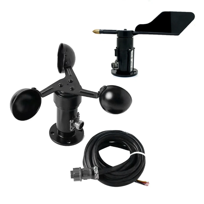
Therefore to interface this we need to make a module which can read the 0 – 5V signals.
Of course the module can be used to read any analog signal! As long as the max. voltage coming into the module is 6.144V, the module can process it. Think of level sensors or light sensors etc.
Design parameters
The ET-AD01 design requirements were:
- ESP32 or ESP8266 controlled.
- Operating at 12V since sensors require 12V to operate
- At least 2 analog input channels which can read up to 5V
- If possible more analog channels for additional sensors
- A few digital input or output channels
- Must fit in a nice looking enclosure, should not look too industrial
- Parts should be available at AliExpress or Amazon for affordable prices, making it as cheap as possible to build
- Firmware should be ESPhome. (Something which is achieved by using the ESP32 / ESP8266 modules)
A number of these parameters are part of the standard parameters of all of our designs.
Practical design
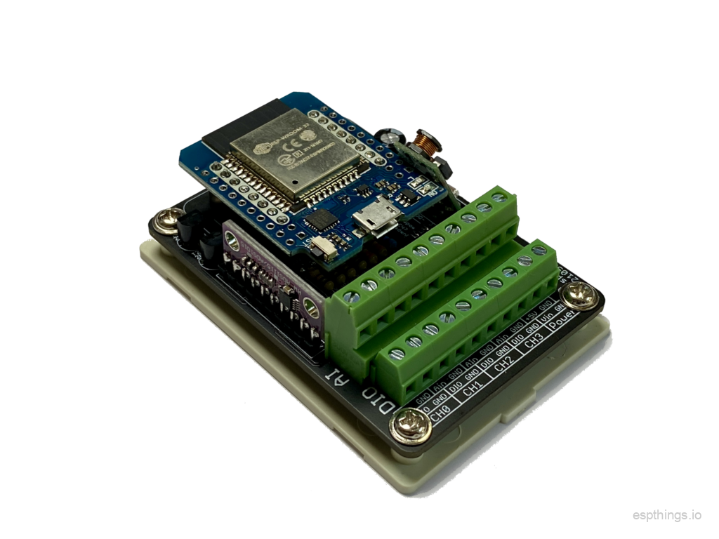
The goal was to have the ET-AD01 design fit in the small enclosure we have used for our previous designs. We also wanted to use as much as possible similar components as in our other designs, therefore we just needed to look for the A/D converter.
Analog to digital converter

When browsing AliExpress for possible options for the A/D converter, and checking at the esphome.io website which converters were compatible, the choice was made to use a ADS1115 based module:
The ADS1115 is a 4 channel 16 bit analog to digital converter with I2C interface. The input voltage can be as high as 6.144V. For more information see the datasheet. ESPhome has built in support for it.
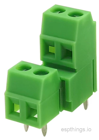
Terminal blocks
To be able to connect all the signals, a single row of terminals would not be enough. The best solution was a double row screw terminal strip, with a slightly smaller pitch than the standard terminal strip. This allowed enough terminals to be fitted for all the signals.
Power supply
The ET-AD01 controller will run from 12VDC, so the voltage regulator which was used in the previous designs is very usable for this design too.
Analog inputs
The controller has a total of 4 analog inputs which can be programmed for input ranges as high as 6.144V.
Digital inputs / outputs
The ET-AD01 controller has 4 digital channels which can be either input or output. The IOs have a current limiting resistor in series between the terminal and the ESP module. This will protect the module against overcurrent, but at the same time allows the input to accept 5V signals without any issue.
Since the unit was designed to interface a wind direction / speed sensor, the decision was made to have the possibility to have one of the digital I/O channels act like a 1-wire connection. This change would allow the connection of the popular DHT sensors, which provide temperature and humidity readings, or the Dallas 1-wire temperature sensors.
Additional IO
The serial port of the ESP module has been made available. This serial port uses 3.3V signal levels. “TXo” means transmit out, data from the ESP module to the outside world, “RXi” means receive data from the outside world to the ESP module. Be careful not to exceed the 3.3V voltage levels, since this might damage the module permanently.
Circuit diagram and PCB
The diagram:
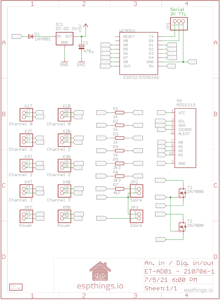
Since the ESP module runs at 3.3V and the analog to digital converter module runs at 5V, the I2C bus requires a level shifter in the form of T1 and T2. To accommodate the change from regular digital I/O to the 1 wire interface, two jumpers were added.
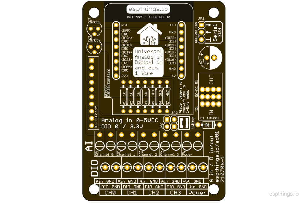
We managed to get it all fit nicely on a PCB with the size of the small enclosure.
Build it!
Bill of materials
See below the list with the components you will need to build the AD01 controller. A number of these items will not be sold in smaller quantities at AliExpress. We will try to use the same components as much as possible in other projects.
We would really appreciate it if you will use the links below to buy the components, since it will give a little bit of commission to us without any additional cost for yourself. These commissions will be used to cover some of the costs involved in the development of the design.
| Reference | Quantity | Description | Affiliate |
| WEMOS1 | 1 | Wemos D1 Mini ESP32 | Link |
| WEMOS1 | 0 | Wemos D1 mini ESP8266 | Link |
| IC1 | 1 | Switching regulator 8-32V in, 5V out | Link |
| X6 | 1 | ADS1115 I2C 16 Bit ADC 4 channel Module | Link |
| T1, T2 | 2 | 2N7000 TO92 Small Signal MOSFET 200 mAmps, 60 Volts | Link |
| D1 | 1 | 1N4001 | Link |
| C1 | 1 | 470µF / 16V 6mm diameter, 2.54mm pitch | Link |
| R1, R2, R3, R4 | 4 | Resistor 1KΩ | Link |
| R5, R6 | 2 | Resistor 3.3KΩ | Link |
| R7 | 1 | Resistor 4.7KΩ | Link |
| JP1, JP2, JP3, WEMOS1 | 1 | Male pin headers. 2.54mm pitch (40 pin) | Link |
| JP2, JP3 | 2 | Jumpers | Link |
| Enclosure | 1 | Enclosure 76x56x29 (AK-N-04) | Link |
| X1, X2, X3, X4, X5 | 5 | KF128A+KF128B 3.81 2P screw terminals | Link |
| PCB | 1 | PCB ET-AD01 | Link |
Putting it together
Like with all other projects, it is the easiest to start with identifying the components purchased as discussed in the blog post. After sorting the components and cleaning the PCB, start with the lowest components first. For this project, we advise to work in this order:
- Resistors
- Diode
- Pin headers
- MOSFETs
- AD converter module
- Electrolytic capacitor
- Screw terminals
- ESP module headers (Use the hints in the soldering blog post!)
- Voltage regulator. Make sure that the voltage regulator is not too tall for the enclosure. You can reduce the height by either by bending the pins of the voltage regulator a little bit.
Once all components are soldered in place, perform a good visual check of all joints, and pay particular attention to possible solder bridges (unwanted solder connections between pins). Do not forget to clean the excess solder flux from the PCB using alcohol!
Software configuration
substitutions:
  devicename: ad01
  long_devicename: "ET-AD01 - 4 channel Ain / DIO."

esphome:
  name: $devicename
  platform: ESP32
  board: mhetesp32minikit

wifi:
  ssid: !secret esphome_wifi_ssid
  password: !secret esphome_wifi_password
  ap:
    ssid: "$devicename Fallback Hotspot"
    password: !secret esphome_ap_password

captive_portal:

logger:

api:
  password: !secret esphome_api_password

ota:
  password: !secret esphome_ota_password

# The Status LED is mounted on the module itself

status_led:
  pin:
    number: 2
    inverted: True

web_server:
  port: 80

i2c:
  sda: GPIO21
  scl: GPIO22
  scan: True
  frequency: 400kHz

ads1115:
  - address: 0x48

# If CH3 is used as 1-Wire (Dallas) interface:
dallas:
  - pin: 18


sensor:
  - platform: wifi_signal
    name: "WiFi Signal $devicename"
    update_interval: 60s

  - platform: ads1115
    multiplexer: 'A0_GND'
    gain: 6.144
    name: "$devicename - CH0 Analog in (0-5V)"
    update_interval: 1s

  - platform: ads1115
    multiplexer: 'A1_GND'
    gain: 6.144
    name: "$devicename - CH1 Analog in (0-5V)"
    update_interval: 1s

  - platform: ads1115
    multiplexer: 'A2_GND'
    gain: 6.144
    name: "$devicename - CH2 Analog in (0-5V)"
    update_interval: 1s

  - platform: ads1115
    multiplexer: 'A3_GND'
    gain: 6.144
    name: "$devicename - CH3 Analog in (0-5V)"
    update_interval: 1s

# Once you know the addresses (ids) of the temperature sensor, you can add the below lines;
# With these lines commented out, you can see in the logs all the sensor ids the controller detects
#  - platform: dallas
#    address: 0x1C0000031EDD2A28
#    name: "Dallas 1-Wire Temperature sensor"

binary_sensor:
  - platform: gpio
    pin:
      number: GPIO05
      mode: INPUT_PULLUP
      inverted: True
    name: "$devicename - CH0 Digital in"
    filters:
      - delayed_off: 20ms
  - platform: gpio
    pin:
      number: GPIO23
      mode: INPUT_PULLUP
      inverted: True
    name: "$devicename - CH1 Digital in"
    filters:
      - delayed_off: 20ms

switch:
  - platform: gpio
    pin: GPIO19
    name: "$devicename - CH2 Digital out"
Connection
Main wiring
Connect the power input (Vin) to a stabilized 12V power supply. The unit will use max. about 250mA, and the sensors will use max. 100mA, so a power supply capable of delivering 500mA should be more than enough.
IO wiring
All IO terminals have a GND connection right next to it, to make it easier to connect sensors our output devices. There is also a +5V connection available, for the sensors which require power to operate.
An analog input channel which is not connected will show a voltage reading, which is noise picked up by the terminals. To prevent these random readings, put a jumper from the analog input terminal to the GND terminal next to it.
If digital channel 3 needs to be used as an 1 wire interface, place both jumpers. In case it is used as a regular digital IO channel, ensure both jumpers are not installed.
ESP32 or ESP8266?
For this project you can use the ESP8266 or the ESP32 based modules. The only difference is that the ESP32 modules have other GPIO pins connected to the pin headers we are using. This results in better boot behavior. With the ESP8266 based modules, you will see some IO pins becoming active, possibly causing issues. The ESP32 based modules do not exhibit this issue. Processing power wise both are more than capable to deal with the IOs….
Final thoughts
The module has been in use for some time now, and is proving to be very reliable. If you run into unreliable readings, then check the voltage regulator.
If you enjoy our designs, please leave a comment and subscribe to our youtube channel, to help us grow the website and channel!
Please subscribe to our newsletter!
