ET-GC01 / ET-GC02 – Geiger counter
Table of Contents
Introduction
As with many designs, there is something which triggers the creation. As part of a bigger design, which will be published in the future, we created a small geiger counter module which can be connected to all of our designs.
Now with the current situation in the Ukraine, with the associated risks in regards to the nuclear power plants, we pulled this design forward, and created a standalone design too.
So this project post is actually a double post, in the sense that we will introduce two designs at the same time. As mentioned, the design was pulled forward for publication, so we do not yet have the final PCBs in our hands. However our prototype is working fine, and there have been no changes made to the diagram, only to the PCB layout and silkscreen.
Design parameters
The requirements were:
- It should be possible to use a wide variety of GM tubes
- Standalone (GC01) or interfacing with previous projects (GC02)
- For the standalone (GC01) design a visual and audible feedback
- For the standalone (GC01) design an option to connect an 0.96″ OLED display
- Adjustable tube voltage
- For the GC02 design an option to use the E10 screw base tubes, or the regular tubes.
- Must fit in a nice looking enclosure, this for safety, since higher voltage will be present
- Parts should be available at AliExpress or Amazon for affordable prices, making it as cheap as possible to build
- Easy to implement in ESPhome.
Practical design

ET-GC02 addon module
The design focuses on the application of Geiger-Müller tubes, therefore we will discuss those first:
Geiger-Müller tubes
A Geiger-Müller tube consists of a chamber filled with a gas mixture at a low pressure of about 0.1 bar / 1.5 psi. The chamber contains two electrodes, which will require a potential difference of 350 – 500 volts for proper operation. The walls of the tube are either metal or have their inside surface coated with a conducting material to form the cathode, while the anode is a wire mounted axially in the center of the tube.
When ionizing radiation strikes the tube, some molecules of the fill gas are ionized directly by the radiation, or if the tube cathode is an electrical conductor, indirectly by means of secondary electrons produced in the walls of the tube. This will initiate a so-called ionizing event, which is multiplied within the gas. The ionizing event will cause the tube to start conducting, which is being detected by the circuit.
When the tube is not conducting, the tube has a very high resistance. When there is a ionizing event the resistance will drop significantly, which allows the current to flow through the tube. If the current through the tube is too high during the ionizing event, the tube will not recover back to the high resistance condition. Therefore a high series resistance is required in the anode connection of the tube. The value of this resistance is normally specified in the datasheet of the tube, together with the required tube voltage. (Some tube data sheets also specify the cathode capacitance.)
The operating voltage curve of the tube has several distinguishable sections. For our purpose, as a simple counter, the tube will be operated in the “plateau” region.
Depending on the construction and gas used, the tube is sensitive to alpha, beta or gamma radiation. Most tubes available are sensitive to beta and gamma radiation only, since alpha radiation has a very low penetration capability. In many cases the tubes sensitive to alpha radiation require a higher potential difference between the anode and cathode, which this design will not be able to produce.
The designs
GC01
Standalone version of the Geiger counter.
GC02

The add-on module design.
If we look at the diagrams of both designs we will see that both are 80% the same, where the GC02 is just missing the voltage regulator circuitry and the ESP module. The other difference is that the GC01 has a tube connection in the form of a screw terminal, while the GC02 has a E10 socket or mounting hole for the tube.


Due to the similarities of the designs, the design which will be discussed in this post is GC01. There are a few items which need to be considered which are different for GC02, which will be discussed separately.
The circuit
Besides the ESP32 or ESP8266 module, the circuit is mainly a 400VDC generator. The generator is a so-called “kickback” generator which is used in a number of other geiger counter designs found around the internet.
The principle is that the NE555 timer output has a variable width pulse, depending on the setting of the potentiometer P1. The frequency of the NE555 is set by R1 / C2, which with the used values is approx. 3kHz. The pulse width varies between 30 and 200µs.
When the output of the timer is high, T2 will start conducting, allowing current to flow through the inductor. This will cause energy to be stored in the ferrite core of the inductor. The polarity over the inductor will be positive at the “VCC” terminal, and negative at the transistor T2 / diode D2 side.
The current through the inductor will rise till the moment the voltage over R5 & P1 is high enough to make T1 conduct. Once T1 is conducting, the timer resets, and the output goes low. This results in T2 to stop conducting. Note that a lower total resistance of R5 & P1, will result in a longer pulse, which will result in a higher energy storage in the inductor. This will cause the output voltage to go up. In the case of the GC02 design, this will make the output voltage dependent on the power supply voltage. A lower power supply voltage will give an higher output voltage with the same potentiometer setting.
Since the current through the inductor is going to zero, the field collapses in the inductor, which causes the voltage to go up. This voltage will have an opposite polarity compared to the polarity when there was a current flowing. Therefore the “negative” side of the inductor is now connected to the “VCC” terminal, with the “positive” side connected to the transistor T2 / diode D2. The voltage over the conductor will be several hundred volts, depending on the pulse width, which will cause D2 to conduct, charging up capacitor C3 to the voltage level of the coil voltage.
Once the voltage over capacitor C3 is equal to the coil voltage, diode D2 will stop conducting, and the energy in the capacitor can only flow towards the Geiger-Müller tube. Once the gas in the tube is ionized by radiation, the capacitor C3 will discharge through R7.
This current will drive transistor T3, which will start conducting, and create an “output” going to “0”, which the ESP module can detect and count.
The ESP module will drive the buzzer and LED, with a short pulse, for every detected radiation particle. Since the buzzer is of the passive type, it will sound like a click. If an active buzzer is used, then a short beeping sound would be sounded. However for authenticity, the click is preferred.
Power supply
The standalone, GC01, design will be able to run from any power supply capable of delivering at least 8 VDC / 500mA. Another option is not to mount the input screw terminals, diode D1 and voltage regulator IC2, and feed the module by connecting a micro USB cable directly to the ESP module.
Build it!
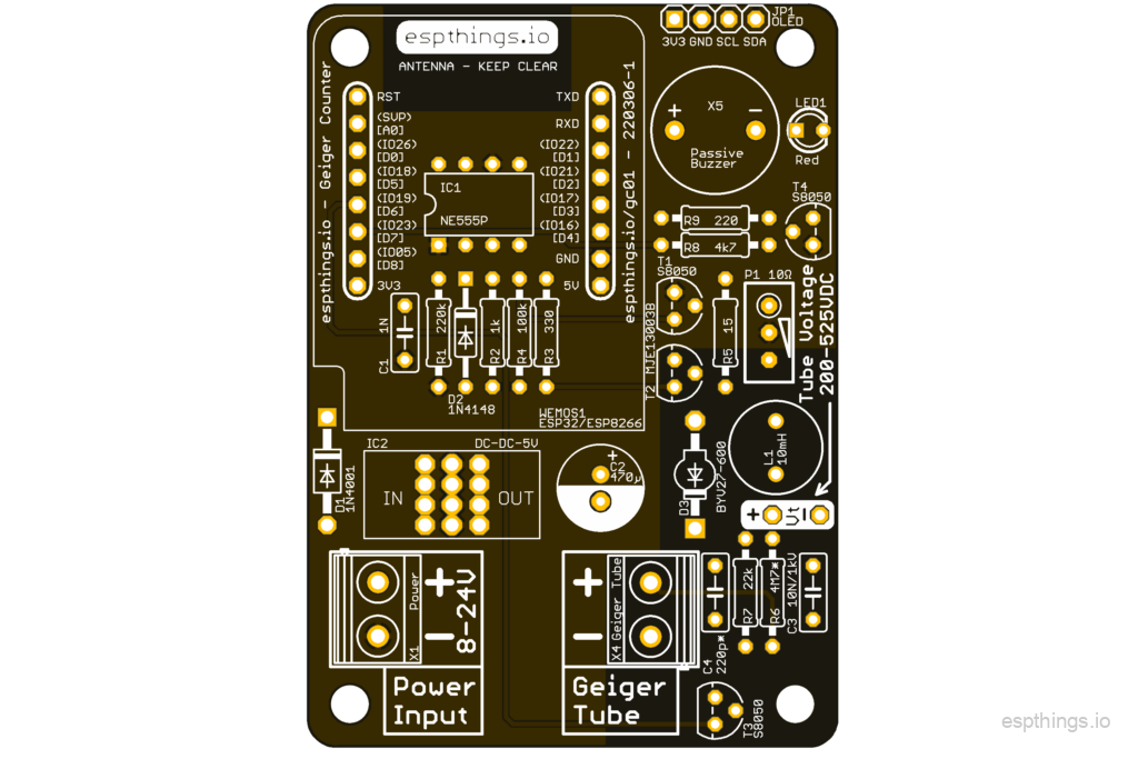
See below the list with the components you will need to build the GC01 or GC02 module. The majority of the components are very similar to the components used in our previous projects. However a few components are very specific for this project, and the quantity required is small. But like before, we will try to reuse the same parts as much as possible in future projects.
We would really appreciate it if you will use the links below to buy the components, since it will give a little bit of commission to us without any additional cost for yourself. These commissions will be used to cover some of the costs involved in the development of the design.
| Part | Value | Device | Description | Link | GC02 |
| C1 | 1N | C050-025X075 | https://s.click.aliexpress.com/e/_AU4fqd | x | |
| C2 | 470µ | C-POL2.5-8.0 | https://s.click.aliexpress.com/e/_AaHvuv | x | |
| C3 | 10N/1kV | C050-025X075 | https://s.click.aliexpress.com/e/_9fXWlR | x | |
| C4 | 220p* | C050-025X075 | https://s.click.aliexpress.com/e/_9jxgCN | x | |
| D1 | 1N4001 | 1N400410 | DIODE | https://s.click.aliexpress.com/e/_AgTh7R | |
| D2 | 1N4148 | 1N4148-10 | https://s.click.aliexpress.com/e/_AK6bEN | x | |
| D3 | BYV27-600 | BYV27-600 | https://nl.aliexpress.com/item/33008922253.html | x | |
| IC1 | NE555P | NE555P | General purpose bipolar Timer | https://s.click.aliexpress.com/e/_AgmLTn | x |
| IC2 | DC-DC-5V | 78XXALI | https://s.click.aliexpress.com/e/_AnTxIN | ||
| JP1 | OLED | PINHD-1X4 | PIN HEADER | https://s.click.aliexpress.com/e/_AXG2X1 | |
| L1 | 10mH | L-6000 | https://s.click.aliexpress.com/e/_9ylja7 | x | |
| LED1 | Red | LED3MM | LED | https://s.click.aliexpress.com/e/_AfAY1B | |
| P1 | 10Ω | P3296W | https://s.click.aliexpress.com/e/_AS4FXB | x | |
| R1 | 220k | R0207/10 | Vishay S105K reference resistor. | https://s.click.aliexpress.com/e/_9zwZW9 | x |
| R2 | 1k | R0207/10 | Vishay S105K reference resistor. | https://s.click.aliexpress.com/e/_9zwZW9 | x |
| R3 | 330 | R0207/10B | Vishay S105K reference resistor. | https://s.click.aliexpress.com/e/_9zwZW9 | x |
| R4 | 100k | R0207/10B | Vishay S105K reference resistor. | https://s.click.aliexpress.com/e/_9zwZW9 | x |
| R5 | 15 | R0207/10 | Vishay S105K reference resistor. | https://s.click.aliexpress.com/e/_9zwZW9 | x |
| R6 | 4M7* | R0207/10B | Vishay S105K reference resistor. | https://s.click.aliexpress.com/e/_9zwZW9 | x |
| R7 | 22k | R0207/10 | Vishay S105K reference resistor. | https://s.click.aliexpress.com/e/_9zwZW9 | x |
| R8 | 4k7 | R0207/10 | Vishay S105K reference resistor. | https://s.click.aliexpress.com/e/_9zwZW9 | |
| R9 | 220 | R0207/10B | Vishay S105K reference resistor. | https://s.click.aliexpress.com/e/_9zwZW9 | |
| T1, T3, T4 | S8050 | TO92-NPN-S8050 | NPN TRANSISTOR | https://s.click.aliexpress.com/e/_Asf3aH | x (2x) |
| T2 | MJE13003B | TO92-NPN-MJE13003 | NPN TRANSISTOR | https://s.click.aliexpress.com/e/_AeVxyt | x |
| WEMOS1 | ESP32/ESP8266 | WEMOS-D1-MINI-ESP32 | WeMos DEV board | https://s.click.aliexpress.com/e/_A1rukH | |
| X1 | Power | SCREW-2-5.08 | Screw terminal – 5,08mm pitch | https://s.click.aliexpress.com/e/_9H8Va7 | |
| X4 | Geiger Tube | SCREW-2-5.08 | Screw terminal – 5,08mm pitch | https://s.click.aliexpress.com/e/_9H8Va7 | |
| X5 | Passive | BUZZER | https://s.click.aliexpress.com/e/_AKrU09 | ||
| ENC | Enclosure for GC02 | https://s.click.aliexpress.com/e/_AZFr0r | |||
| PCB-GC01 | PCBway PCB | PCB for ET-GC01 | Order the ET-GC01 PCB here! | ||
| PCB-GC02 | PCBway PCB | PCB for ET-GC02 | Order the ET-GC02 PCB here! | x | |
| G-Tube | M4011 geiger tube | https://s.click.aliexpress.com/e/_A0FADz | |||
| G-Tube | J304 geiger tube with E10 Socket | https://s.click.aliexpress.com/e/_APMKUL | |||
| E10 socket | E10 Socket for PCB mounting | https://s.click.aliexpress.com/e/_9RhgAP | |||
| E10 socket | E10 socket alternative (requires some mod) | https://s.click.aliexpress.com/e/_AbMU3h |
Putting it together
Like with all other projects, it is the easiest to start with identifying the components purchased as discussed in the blog post. After sorting the components and cleaning the PCB, start with the lowest components first. For this project, we advise to work in this order:
- Resistors
- Diodes
- NE555
- Transistors
- Capacitors
- Screw terminals
- Trimmer potentiometer.
- ESP module headers if applicable (Use the hints in the soldering blog post!)
- Electrolytic capacitor
- Voltage regulator. Make sure that the voltage regulator is not too tall for the enclosure.
- In case of the GC02 design, mount either the E10 screw base with the center connection to the pad marked “+”, or solder the tube directly to the PCB. Ensure the end marked with a “+” is directly connected to the PCB, and use a small / thin insulated wire from the other end of the tube, to the connection labeled “-” on the PCB
Once all components are soldered in place, perform a good visual check of all joints, and pay particular attention to possible solder bridges (unwanted solder connections between pins). Do not forget to clean the excess solder flux from the PCB using alcohol! This is especially important in the section where the 400V is present.
Tube voltage setup
The voltage generator has a high internal resistance, of approx. 5MΩ. This means that when measuring the voltage with a normal multimeter, which have normally an internal resistance of 10MΩ, the reading will be incorrect, or better, not as expected. The reading on the multimeter will be approx. 2/3 (0.667x) the actual value. So it requires a little bit of math to ensure you setup the voltage correctly.
In the below diagram V1/R1 is the voltage generator, and R2 is the multimeter. As you can see the voltage is split over the two resistors, with 1/3 of the voltage over R1, and 2/3 of the voltage over R2.

Most tubes will require a voltage of 400VDC +/- 20V, and with the knowledge that we have regarding the internal resistance of the voltage generator, we know we need to measure approx. 400V x 0.667 = 265VDC between “Vt+” and “Vt-“. We have verified this reading by using a 100x probe and an oscilloscope, where the 100x probe reads the 400V correctly.
Enclosure for GC02 – add on
For the GC02 a different than our standard enclosure has been used. It is listed in the BOM, but we have also created a 3D printable version.


The small ring slides over the tube to protect the positive terminal of the tube.

The inside of the box has the mounting holes for the PCB and notches to keep the lid in place. Remember that the tube has to be mounted from the back of the PCB when using this enclosure!
You can download the STL files here: GC02-Enclosure
Main wiring
The wiring to the controller, in case the add-on module is used, can be done with normal DuPont style wiring. The power consumption of the module is very low, and will not put a significant load on the main module.
In case the standalone version is used, make sure you use wiring with sufficient insulation to connect the tube. DuPont style wiring is normally not rated for 400V, so please don’t use it. The wire diameter can be small, since the tube current is max. 400V (tube voltage) / 10MΩ (internal resistance of the generator + anode resistor) = 40µA.
Software configuration
Conversion factor
Every G-M tube design will have its own characteristics, which comes out in a different working voltage, anode resistor, cathode capacitor. Another factor is the sensitivity of the tube. In other words, what does it mean when the tube detects on radiation particle; how much radiation is detected? This is the conversion factor of the tube.
Of a number of tubes you can find this conversion factor in the datasheets / online, but sometimes not. If it is known, it can be used to show the radiation in normal units, like µSv / hr. (See the YAML configuration where the conversion factor is used.) Using the converted reading, an alarm level can be setup, and possible automated actions can be taken.
But if you do not have the conversion factor, the conversion to µSv/hr can not be done (correctly). The option which is left in that case is just use the counts per minute (cpm) . A reading under normal circumstances is taken, which is then considered the background radiation level. If this reading goes up by 5x or more, then you know there is an abnormal circumstance, and an alarm condition can be generated.
ESP32 or ESP8266?
For this project, you can use the ESP8266 or the ESP32 based modules. There is no specific requirement for processor speed, so the ESP8266 modules are more than sufficient for this application.
ESPHome configuration
substitutions:
  devicename: et-gc01
  long_devicename: "ET-GC01 esp32"

esphome:
  name: $devicename

esp32:
  board: esp32dev
  framework:
    type: arduino

wifi:
  ssid: !secret esphome_wifi_ssid
  password: !secret esphome_wifi_password
  ap:
    ssid: "$devicename Fallback Hotspot"
    password: !secret esphome_ap_password

captive_portal:

logger:

api:
  password: !secret esphome_api_password

ota:
  password: !secret esphome_ota_password

web_server:
  port: 80

sensor:
  - platform: pulse_counter
    pin: GPIO16
    name: "$long_devicename CPM"
    id: geiger_counter
    unit_of_measurement: "CPM"
    on_raw_value:
      - sensor.template.publish:
          id: radiation_level
          state: !lambda 'return x / 151;'
  - platform: template
    name: "$long_devicename Radiation Level"
    id: radiation_level
    unit_of_measurement: "µSv/h"
    icon: mdi:radioactive
    accuracy_decimals: 5

binary_sensor:
  - platform: template
    device_class: safety
    name: "$long_devicename Radiation Warning"
    lambda: |-
      if (id(geiger_counter).state > 100) {
        // High Count.
        return true;
      } else {
        // Normal Count.
        return false;
      }
Final thoughts
The goal was to design a simple, cheap circuit to measure the radiation with a G-M tube. We looked at existing designs / kits available online, and in general we think our design is considerably cheaper.
There is a wide variety of G-M tubes available on the internet, some of them NOS (new old stock) tubes from the former USSR, and a variety of Chinese made tubes on AliExpress. Most tubes will work on a voltage of approx 400VDC, and their anode resistance are all about 4.7 – 5.6MΩ. However their sensitivity is from very insensitive to very sensitive. The circuit has been tested with a Chinese J304, which is giving nice background readings, and a Russian Si3BG tube which is one of the least sensitive tubes with low background readings.
For best readings, place the tube, if possible, in a vertical direction outside. Even in the window there will be a different reading compared to outside, since most glass types contain a metal containing film in between the layers, which will decrease the sensitivity of the counter.
If you enjoy our designs, please leave a comment and subscribe to our youtube channel, to help us grow the website and channel!
Please subscribe to our newsletter!

I was intrigued by your GM-reader design, I purchased both types of PCBs as well. I am now fitting my “prototype” and have tried to print out the schematics from the pictures on the web.
The images are extremely poor quality and not suitable for filing in the device documentation folder.
Therefore, I ask you to add high quality images of the schematics or maybe even attach the schematic files from KiCAD.
Thank you
Hi, the resolution of the images is fine. Just open the image in a new tab or zoom.