Soldering
Soldering is a fundamental skill you should master if you would like to build our projects. In this tutorial, we outline the basics of soldering. You’re worried things might get complicated? Well, just carefully read the instructions below, and you’ll have no problem building our projects in no-time!
Table of Contents
What is soldering?
Soldering is a way to make an electrical connection between two conductors. In our case that means between the leads or pins of the components and the PCB. To make a reliable and good connection we use a soldering iron which can reach the melting temperature of the solder wire, and has enough power to heat up the PCB quick enough. The solder we use has a resin core, which acts like a flux. Do not use acid based flux, which is used for plumbing! Also only use solder wire rated for electronics connections!
OK, that was the formal part of this post. Now let’s get into how you can solder the projects in the best, and easiest manner.
Tools required:
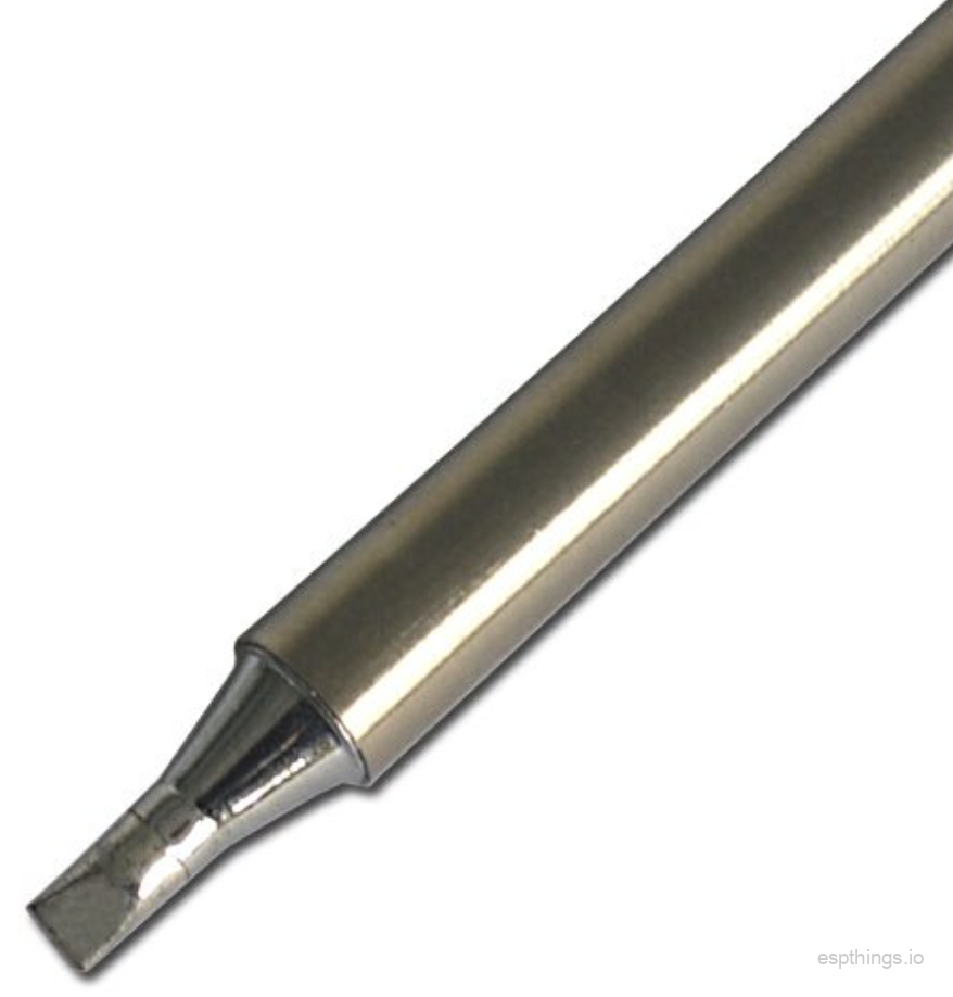
T12-D24 tip
- Soldering iron with a stand and soldering iron cleaner. If you have multiple tips for your soldering iron, pick the chisel style tip, of approx. 1.5mm (1/16″) wide. Sharp pointy tips are not ideal for the components we use in our projects.
- Solder wire with rosin core. There are a number of options, see our Tools and equipment page
- Some sharp electric wire cutters
- Preferably a PCB holder / clamp
- Needle nose pliers and / or the component lead bending tool
- Some isopropyl (> 90%) alcohol with a toothbrush
- And of course one of our PCBs with all the required components!
Note: If you have already a soldering iron, or you want to buy a different type than we recommend on the Tools and equipment page, then make sure that the soldering iron has a power of 40 – 60W, and has temperature regulation in the correct range for the solder wire you plan to use. A power of 40 – 60W ensures that the soldering iron is capable of keeping it at the right temperature, when heating up the PCB pad and the component leads.
Avoid static electricity
Make sure that you are not wearing your favorite woolen sweater or socks, since this will create static electricity build up, which will damage your components. It is best just to wear non synthetic clothing, like cotton when assembling anything electronic. A dry environment is also a good source to build up static electricity, so it is better to be a bit warmer and humid, than dry and colder!
Sort all components
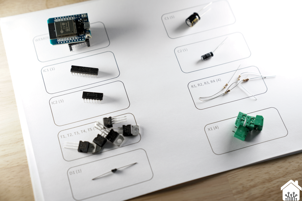
Start with identifying all the components with their values. If needed take a sheet of paper, put the components on the paper and write near the component the value for easy identification. You can include the component references, like R1 / C3 / IC1, so it is easy to find out where they go.
Clean the PCB
Clean the PCB on both sides with some alcohol, and the brush. Normally this is not really needed, especially if you have just received the PCBs from the supplier, and there is no dust or other contaminants on them. But it never hurts to do it anyway! Clamp the PCB with the component side (top side) facing up in the holder if you use one.
Set the correct temperature
Switch on your soldering iron at this moment, set the temperature to 350 – 360 C if you are using solder wire which contains lead, or around 390 C for lead free solder wire. If you use a specific type of solder, like the Kester K100LD, follow the recommendations of the manufacturer. (Kester K100LD works very nice at 330 – 340 C) Once the soldering iron has reached the set temperature, clean it with the cleaner, and right after apply some solder to the tip. Cover it up completely in a layer of solder. This will help to extend the lifetime of your soldering iron tip!
Bending and mounting components
The best order to mount components is from “low” to “high”. In general the resistors are the lowest components on the PCB, in rare cases this might be different.

Bend the resistor leads using the tool, or the needle nose pliers, and put it in its right place on the PCB. If you are using the clamp, you have now the option
to solder the component in place from the top. If you do not use the clamp, turn the PCB over, keeping your finger on the resistor / part you just put
in its place. Once upside down, bend the component leads outwards, so the component cannot fall out.
Your first solder joint
Now you are going to make the solder joint. Use this routine for a good result:
- Clean your tip using the soldering iron cleaner. Make sure the tip is free of anything black / dirt.
- Apply a little bit of solder wire to your tip. Do not apply a lot, just enough to cover it.

- Place the tip of the soldering iron on the PCB pad, making sure you have the side where you just applied the solder facing the PCB, slightly pushing towards the lead sticking out of the pad.
- Wait for 0.5 – 1.0 second, and then apply a little bit of solder wire on the other side of the lead sticking out of the PCB, ensuring the solder touches the component lead and the solder pad on the PCB.
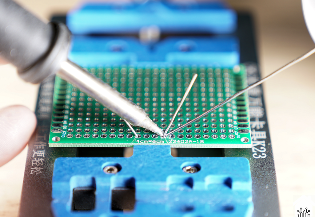
Right way

Wrong way
- Once you see the solder flow around the lead and the pad, remove the solder wire, and about 0.5 – 1.0 second later remove the soldering iron tip from the pad and lead.
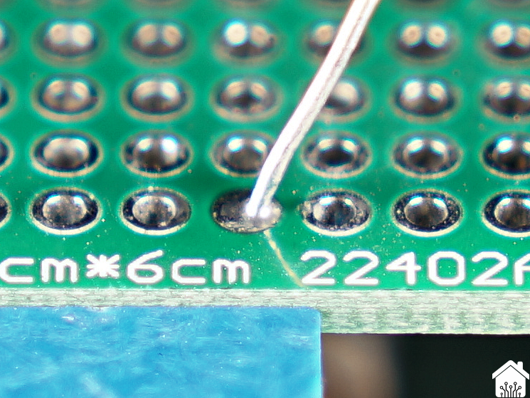
- Wait for about 2 – 3 seconds to let the joint cool down enough, and inspect it. You should see something like this:

Good joint
- If your joint does not look like one of the above, try to reheat the joint by just putting your soldering iron back to the PCB pad and the lead. Sometimes it helps to clean your tip first and apply a bit of fresh solder on the tip.
Not enough solder
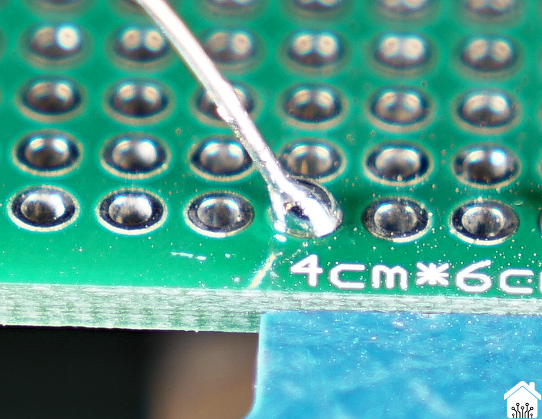
Too much solder
- In case you cannot get the solder to flow nicely, and you follow the steps above, then you have most likely the wrong temperature on your soldering iron tip. If it is too cold, you will have a harder time getting the solder the melt, even if you just touch the solder wire to the tip. If it is too hot, you can easily get the solder to melt, but you see the rosin flux very quickly evaporate, and the solder looks not smooth.
- Solder now the remaining leads of the component you are placing on the PCB.
- Once all joints have been made, use the cutter to cut the leads sticking out just above the solder joint. If you see the lead move in the joint during the cutting, or you see a small gap after the cutting around the lead in the solder joint, reheat the joint briefly to make sure the joint is good.
- If you solder the connection from the top, it is possible that if you have applied minimal, but sufficient, amount of solder to the joint, that the hole is not fully filled up when looking from the bottom of the PCB. You can choose to solder the joint from the bottom too, or you can leave it like this.
- Repeat the steps above for all components, working from lowest to highest / tallest components.
Avoid damaging components
Be careful with the MOSFETs and ICs used in our projects. These are more sensitive to static electricity and therefore it is best avoid as much as possible touching the pins. If you do touch them, make sure you touch all of them at the same time if possible, or use a piece of wire to connect all leads / legs together. If you got your ICs in the plastic tube, or on the foam, leave them in there until the moment you are going to mount them. This will prevent unneeded damage.
The pin headers / female headers in our projects you do not need to trim after soldering.
Some tips how to solder specific types of parts
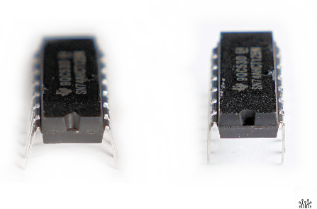
When you buy an IC (integrated circuit / chip) the pins will be bend but not far enough to immediately fit in the PCB. This is done for the automatic insertion of these during factory assembly. To bend the pins a bit further, put the IC on its side with the pins touching your worktable / mat, and slowly push the body of the IC so that all pins bend at the same time at the same angle. Try to keep the angle slightly larger than 90 degrees, since this will allow the IC to stick in the PCB easier. (It will not as easily fall out when flipping the PCB over). If you decide to use a socket for your ICs, then bend the pins as close to 90 degrees as possible (as shown on the right).
Our projects all use a version of the ESP32 or ESP8266 modules. These are plugin modules, which normally have the “male” headers (pins) connected to the module, and the “female” headers (holes) on the project PCB. This can be a challenge to solder in such a way that they easily fit.
Luckily there is a simple way to get the male headers exactly in the right position and angle for the insertion in the female headers on the PCB. With every module you normally receive the male and female headers. Create the following setup with these headers:
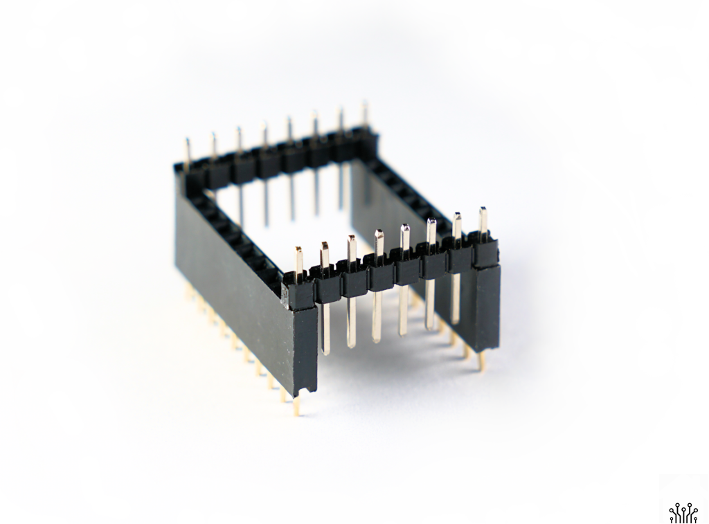
Then place the module on top of the male headers and solder the pins to the module.
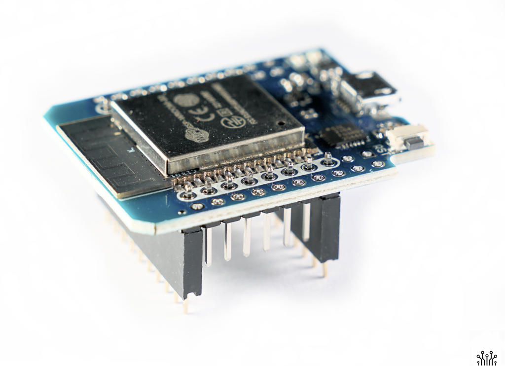
After this, you can put the female headers on the male headers, and then use that combination to put them in place on the project PCB. Solder the female headers in place with the module still attached, so you know it will always be aligned when you remove / insert the module. If your module came with female headers with long pins and short pins, try to use only the ones with the short pins… Otherwise you end up cutting the long pins after soldering.
Please subscribe to our newsletter!
[…] A Soldering iron. More about soldering here […]
[…] project it is the easiest to start with identifying the components purchased as discussed in the blog post. After sorting the components and cleaning the PCB, start with the lowest components first. For […]
the tip about soldering headers is really good. i have not seen that one before.
WS2815 How should I connect this LED with 4 pin connection to the pcb?